Bostig Installation - Part 2
If you missed Part 1 of the install be sure to check it out here.
At this point in the conversion we're basically left with installing all new parts into the van, which is a welcome change. Dealing with rusty bolts, applying messy cleaners, dirt falling in your face, etc., decreases substantially. Most things are pretty easy by now. "Put bolt A onto part B." Stuff like that.
NOTE: This article is NOT intended to be a step-by-step guide like some of our other posts are. It's purpose is to show the overall process of the Bostig engine conversion.
Just like Part 1, if you have a specific area of interest use these links to page-jump to the appropriate topic:
SKILL LEVEL: Moderate / Difficult
Before starting, please read our Disclaimer. By using this website you agree to these terms.
Zetec & Transaxle Install
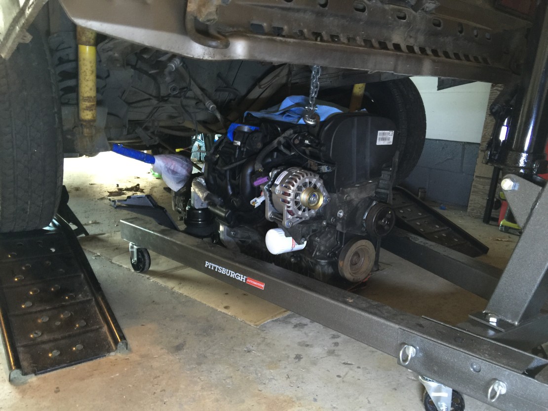
The moment is here, installing the Zetec into the van!
I initially slid the engine under the van using a sturdy piece of cardboard, then, hoisted everything into its approximate location. After that, you jack into place and re-attach the stock front transaxle mount using a spacer, drill some holes for the custom Bostig engine cradle, and eventually get the CVs into position too.


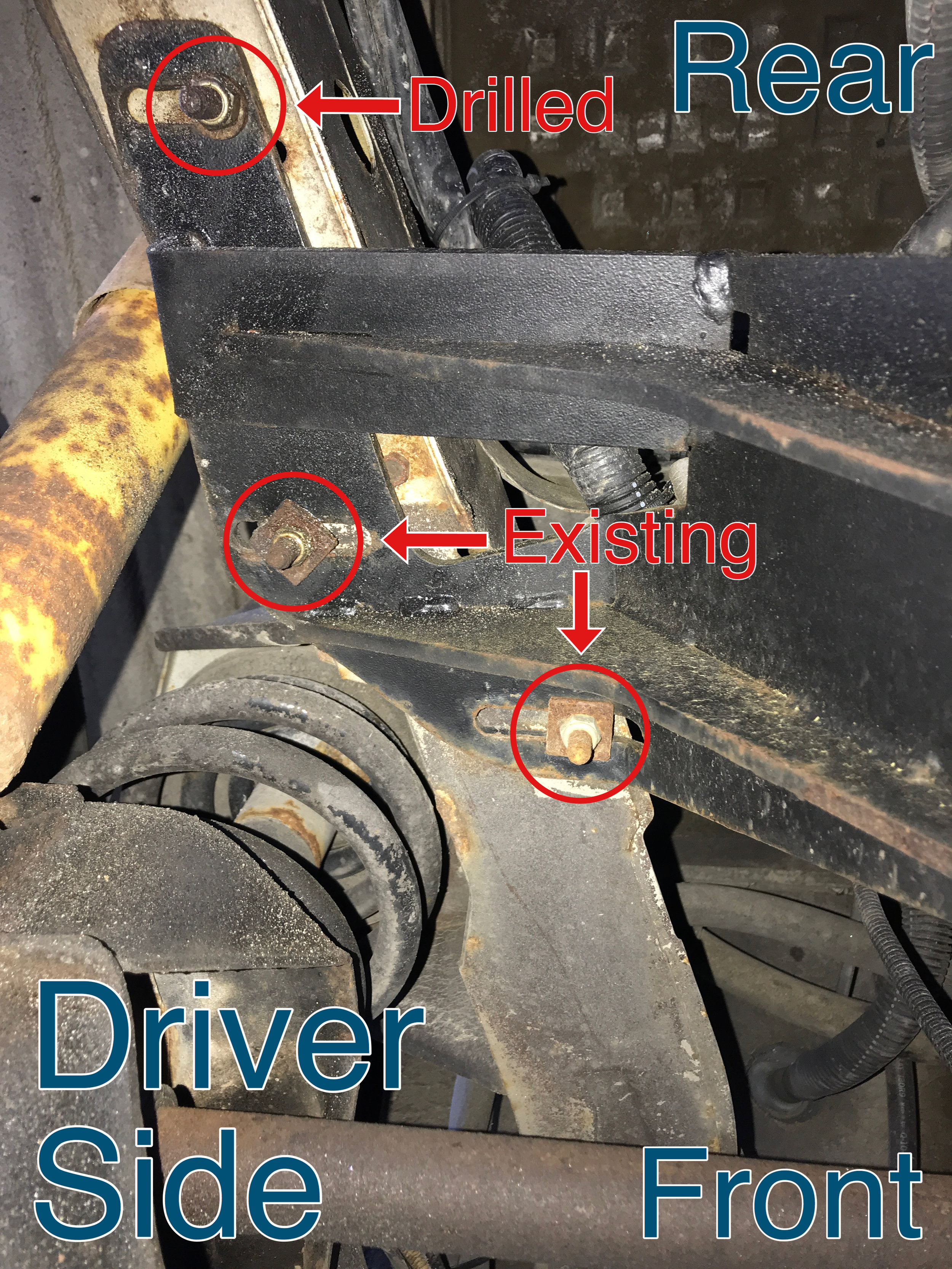
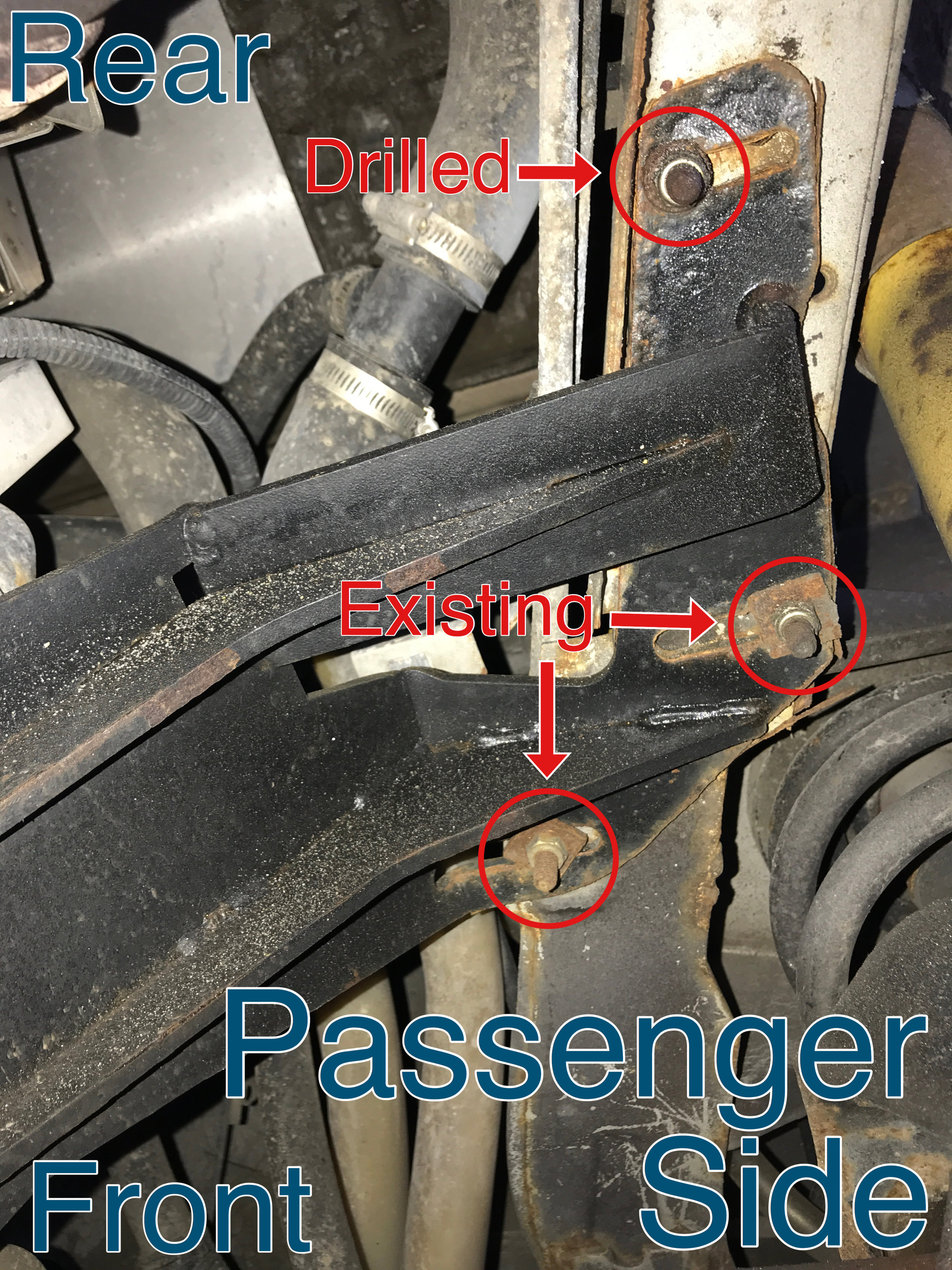
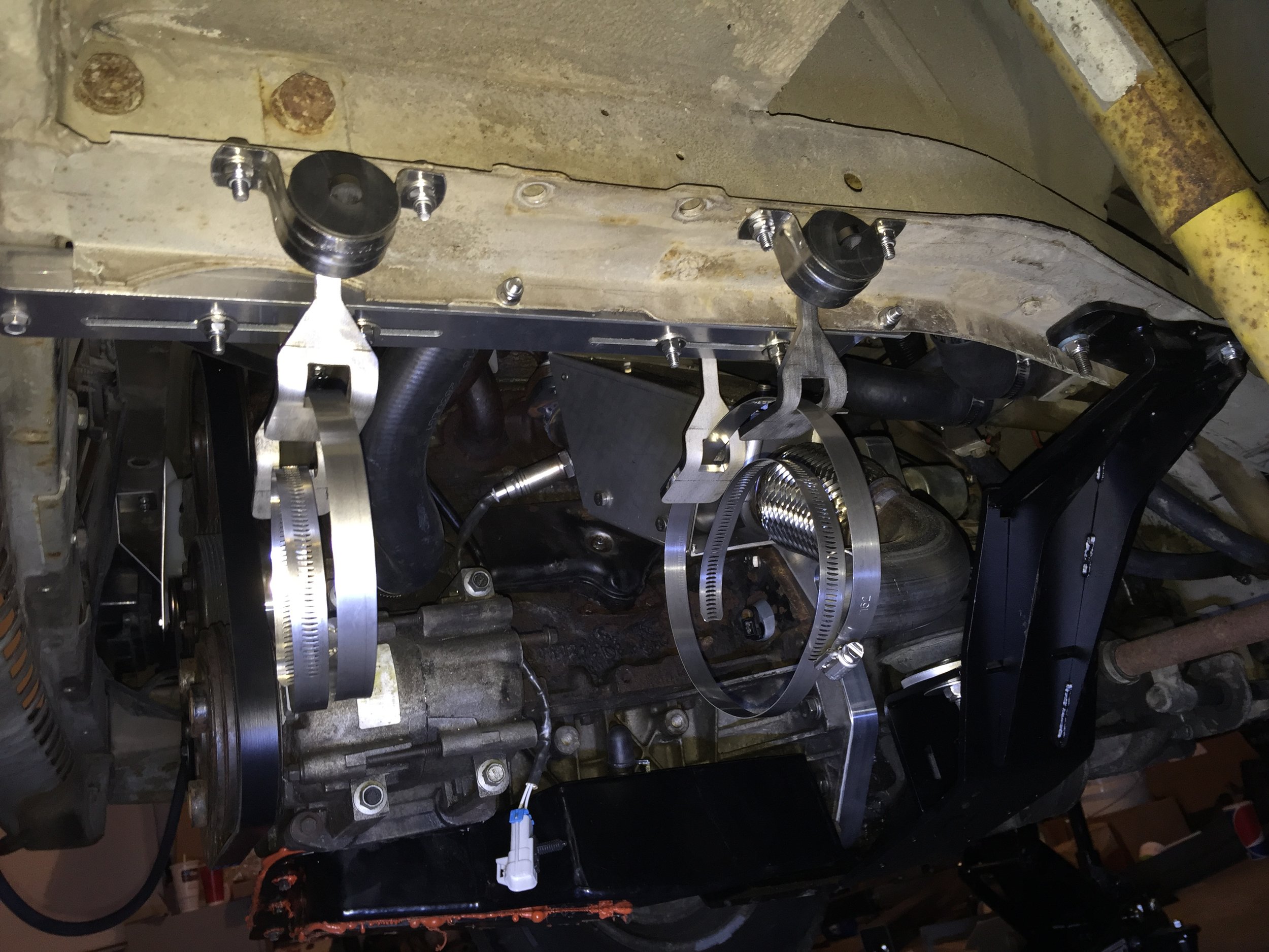
For the engine cradle mounting, on each side you use two existing holes in the Vanagon frame, and then drill a third one. The two existing holes were not obvious to me because there are lots of other holes in the area, not to mention I realized I had some dirt hiding mine at first. The two existing holes are the front-most ones, and the third ones you drill out are the rear-most mounts. Here's a quick video that hopefully clears things up.
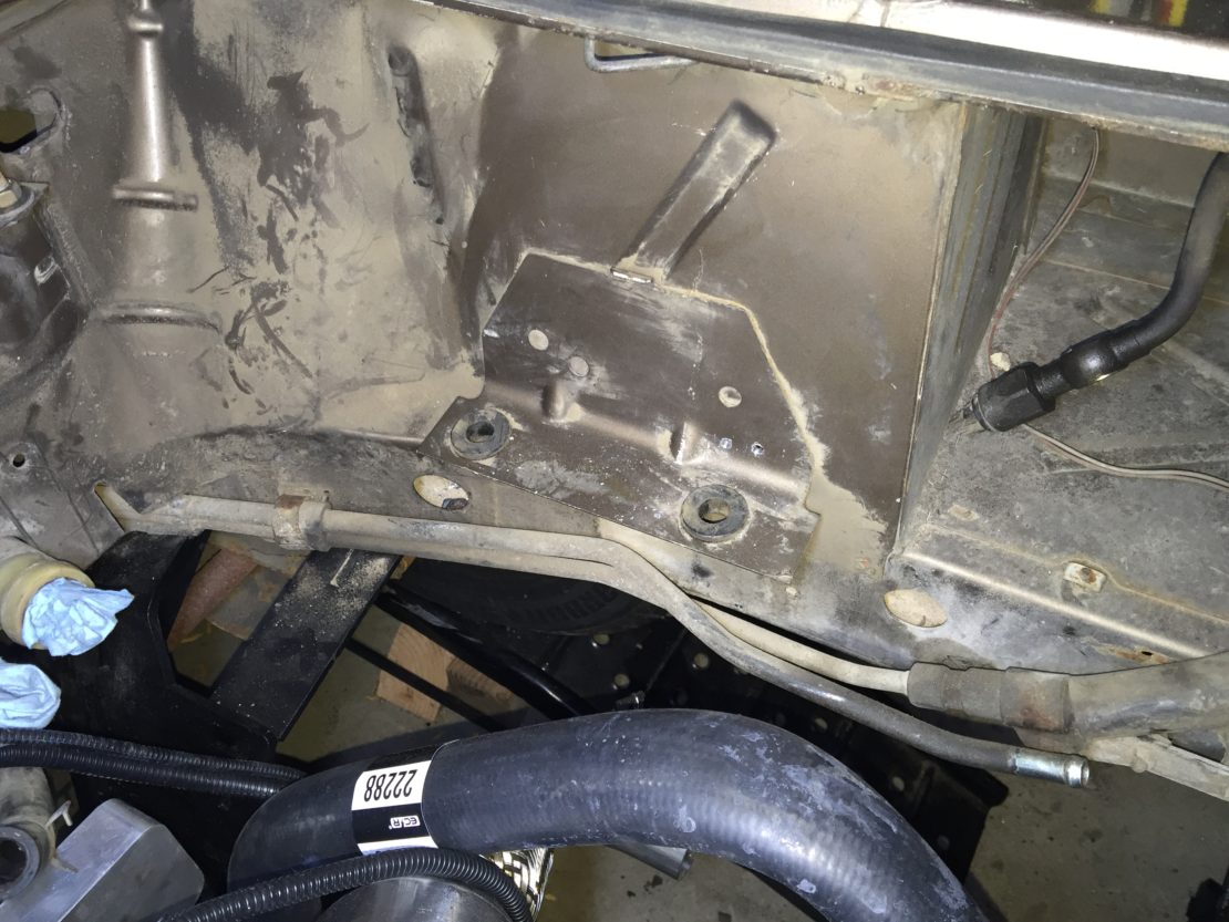
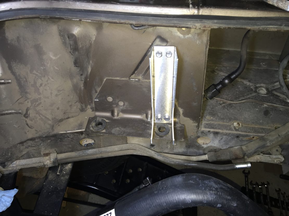
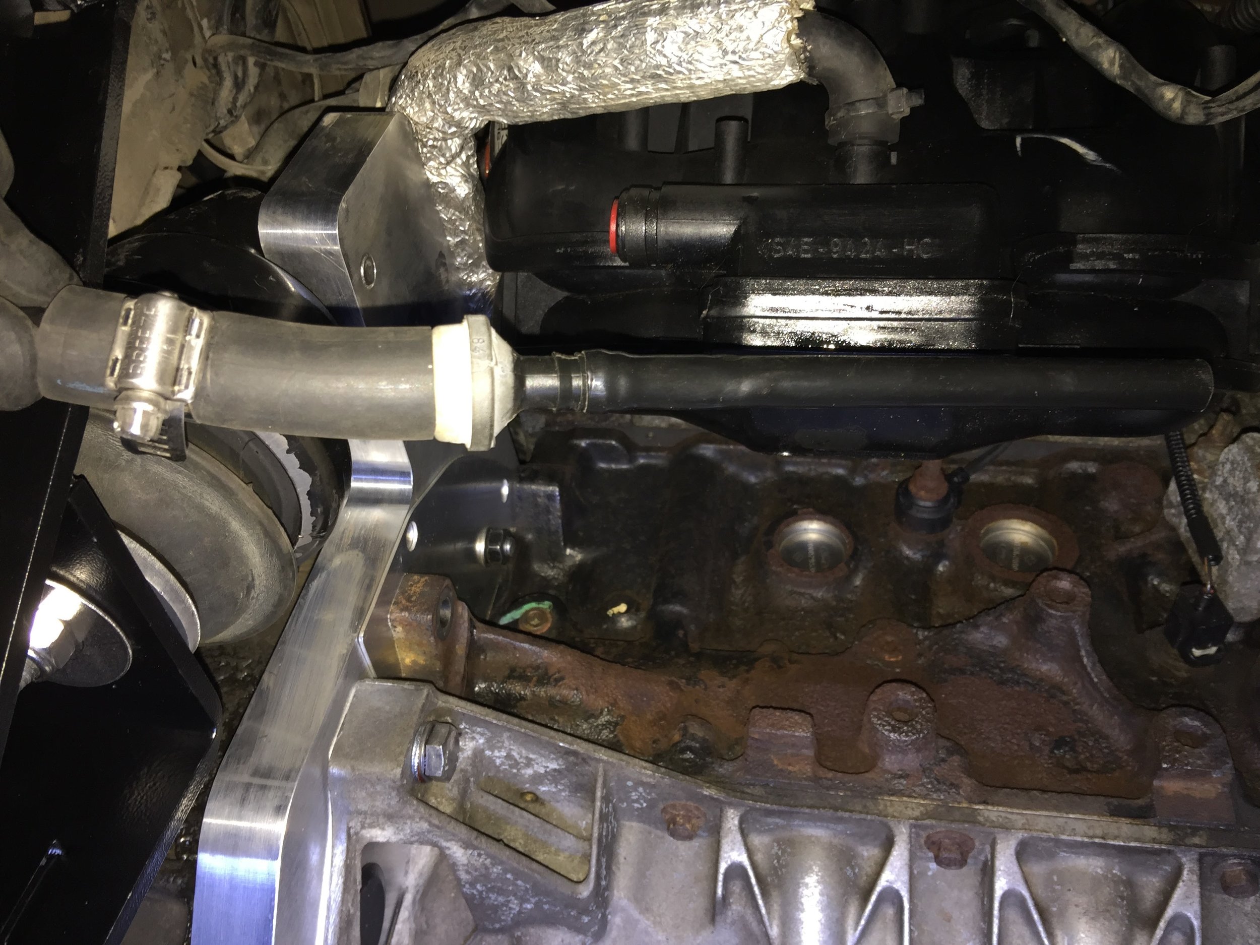
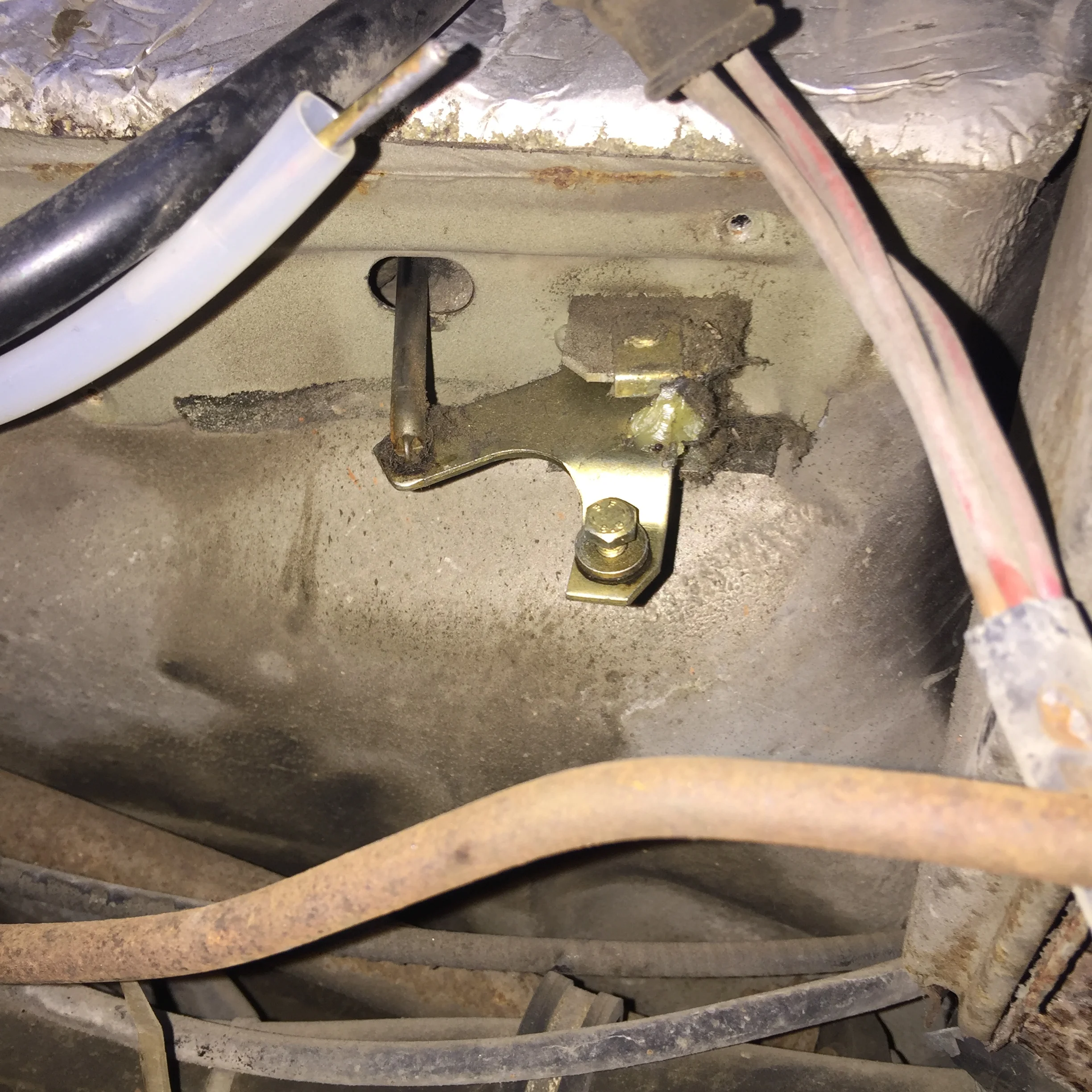
To further clarify what the video showed, here's a couple of pictures post-install, obviously:
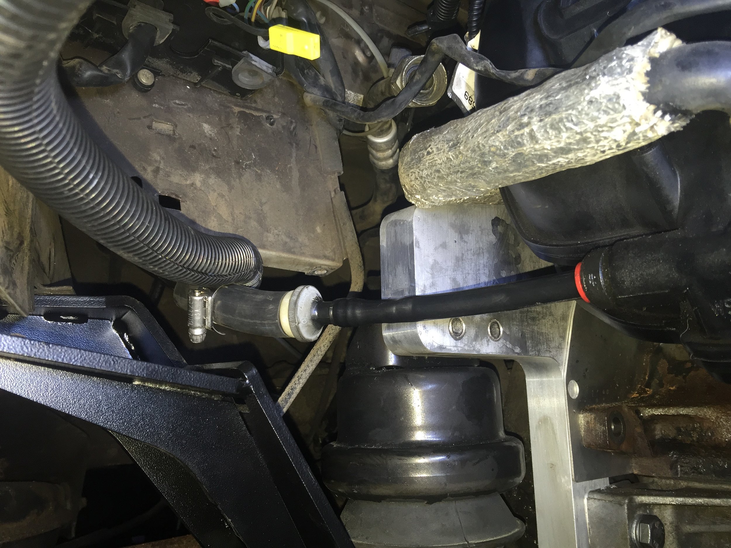
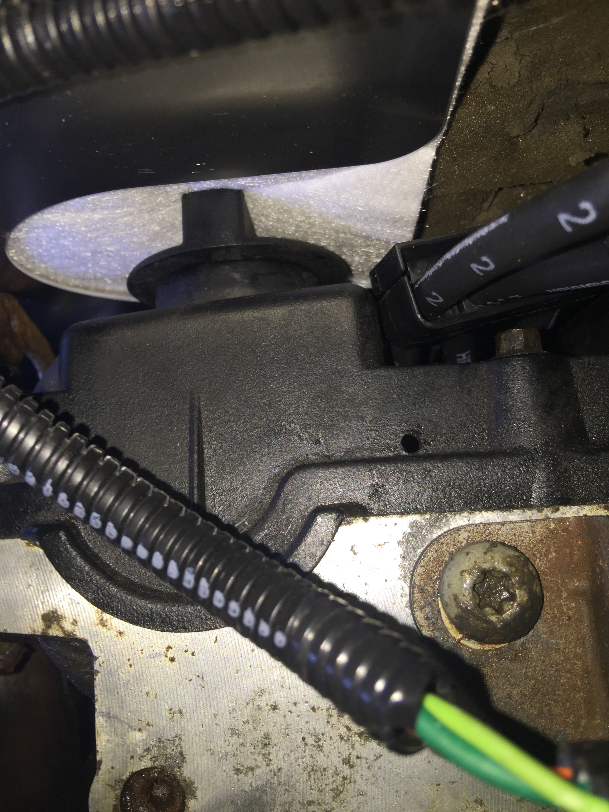
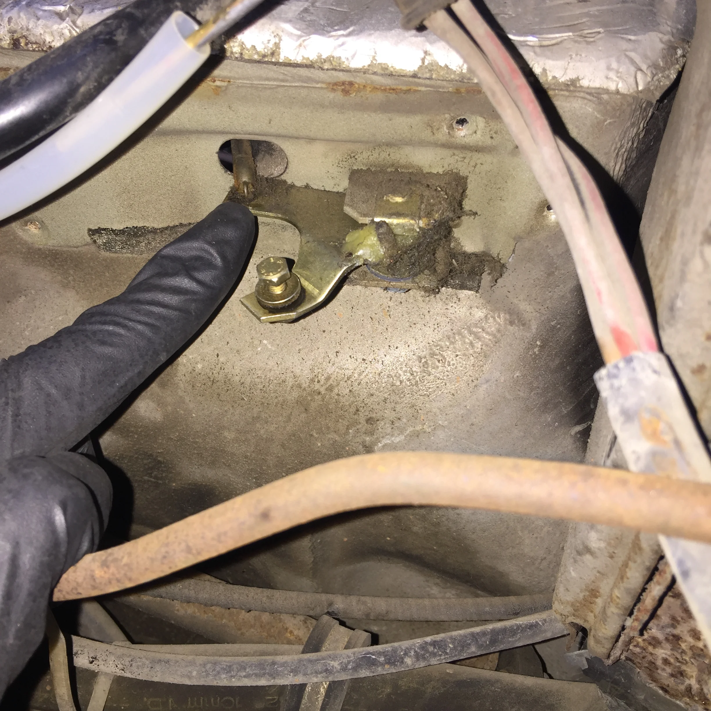
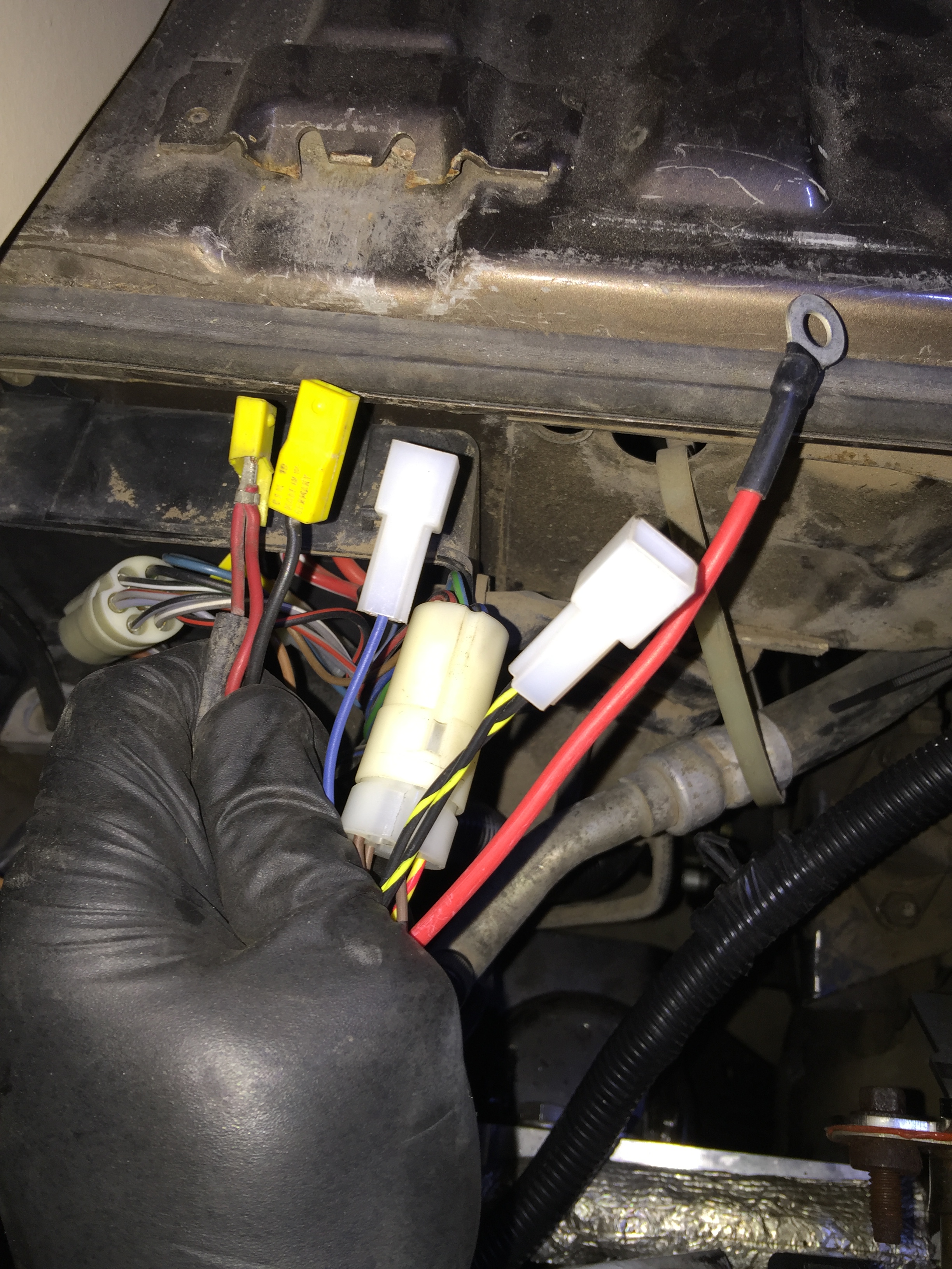
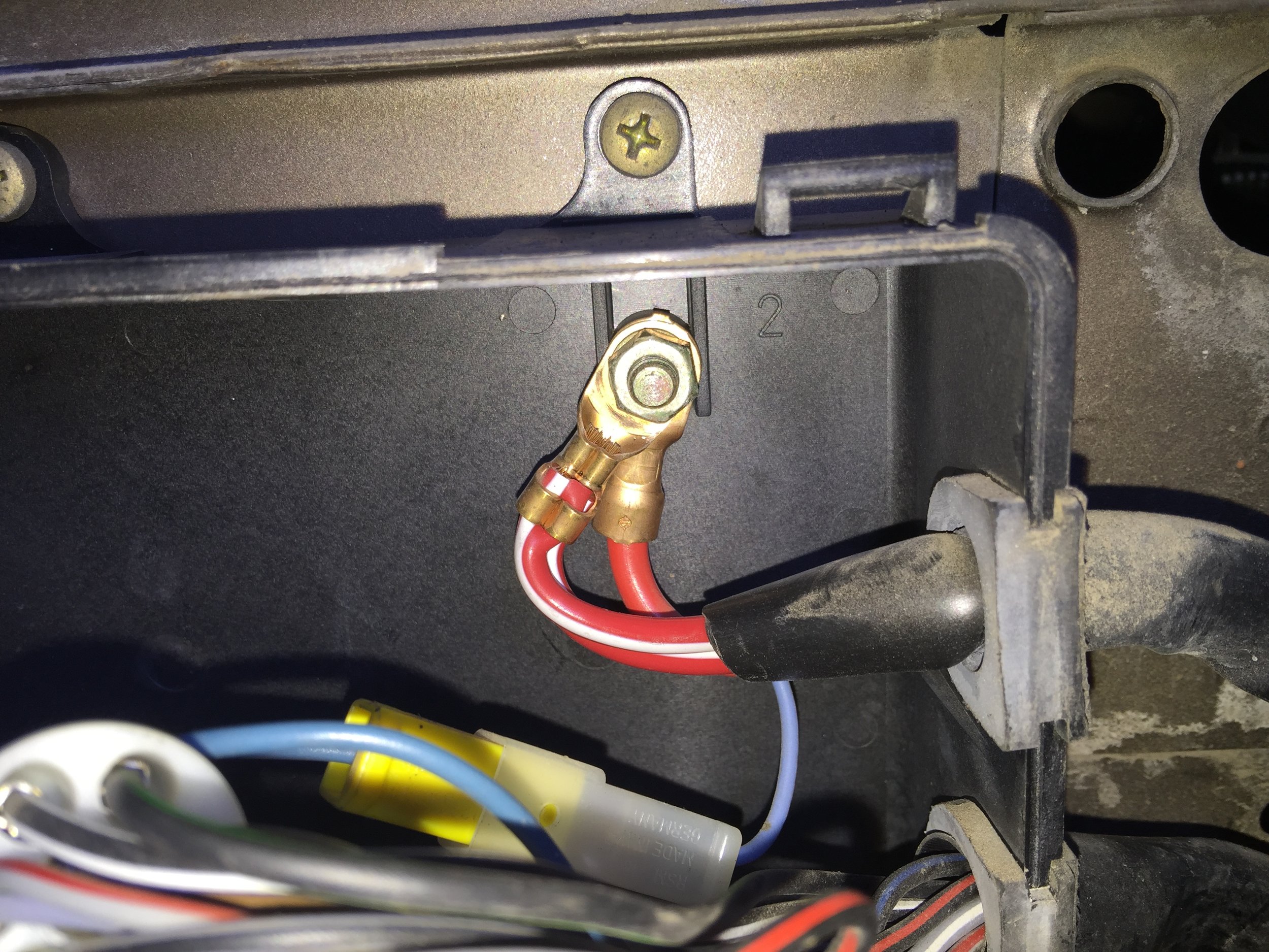
One thing I came across by pure chance after the conversion was totally done, was that I had accidentally used different bolt holes for the front transaxle mount. In the first pic below you can see there is an extra bolt hole between the transaxle and the large grounding wire. In the second pic, after I re-installed, the transaxle is now directly next to the large wire instead of having the space from before. This is approximately two inches of a difference.
Apparently there are two sets of four, equally spaced holes available for the trans mounting. When I re-installed I simply jacked it in place and put the bolts in with no second thought, not realizing I had two options. I asked Bostig and they said I should move it over to the original holes. They also said there is now a note in the updated manual about this, as someone else did the same thing around the same time as me. Glad I wasn't the only one! Ha.


We drove it like this for 2,000+ miles before noticing, so apparently it's not a huge deal. In hindsight, I do remember thinking the stick-shift was off a little when I first drove it with the Zetec. This makes sense considering the shift linkage was taking a slightly different line. After I re-installed everything using the original holes, my shifting was nice and smooth like it had originally been. Problem solved!
Clutch Slave Cylinder
With your new Bostig adaptor plate in place, you'll need a 13mm stubby wrench (or some other short / bent wrench) to reinstall the rear mounting bolt. I used a piece of tape to hold the bolt to the wrench so I could get the nut on from the top. Sorry, didn't get the greatest pics for this.


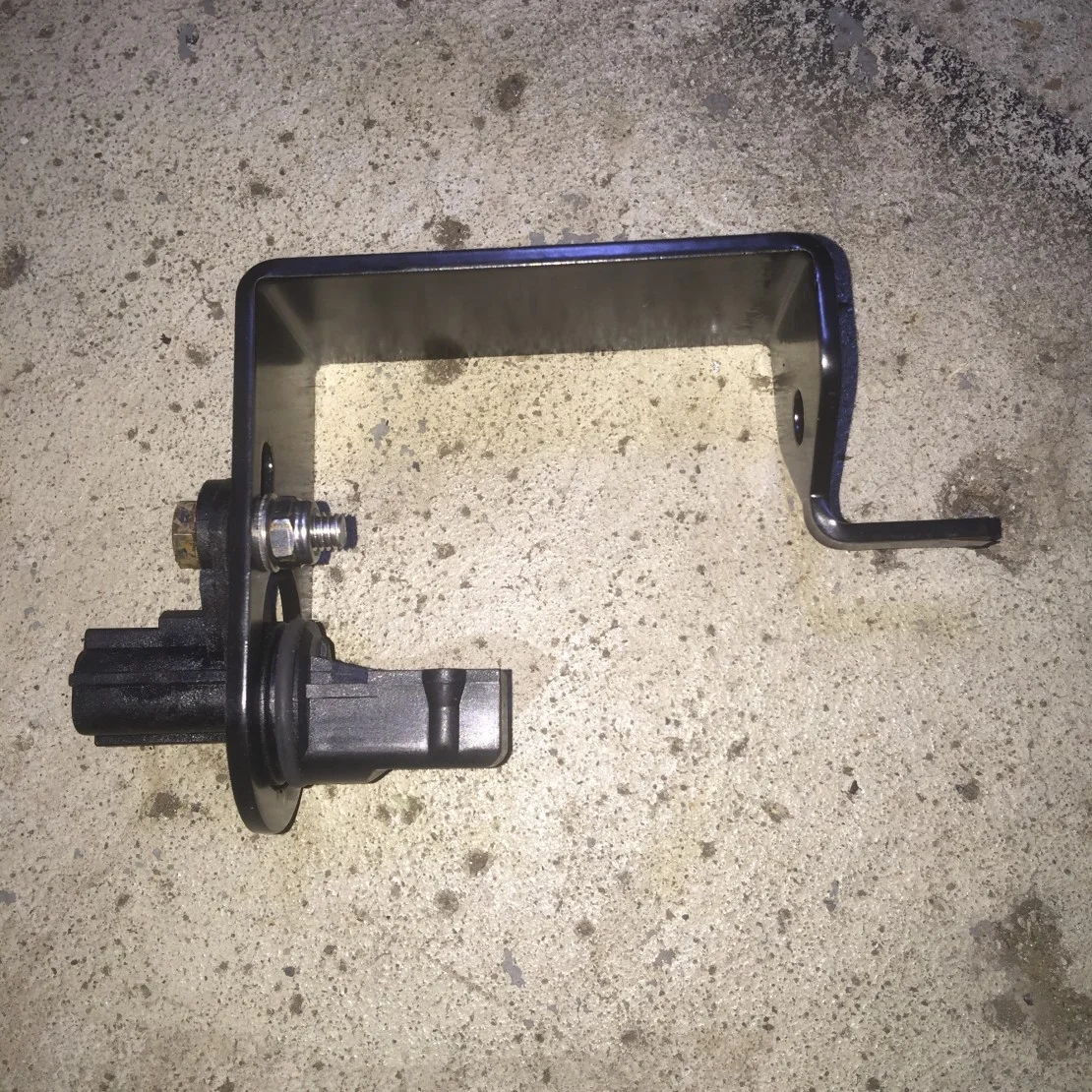
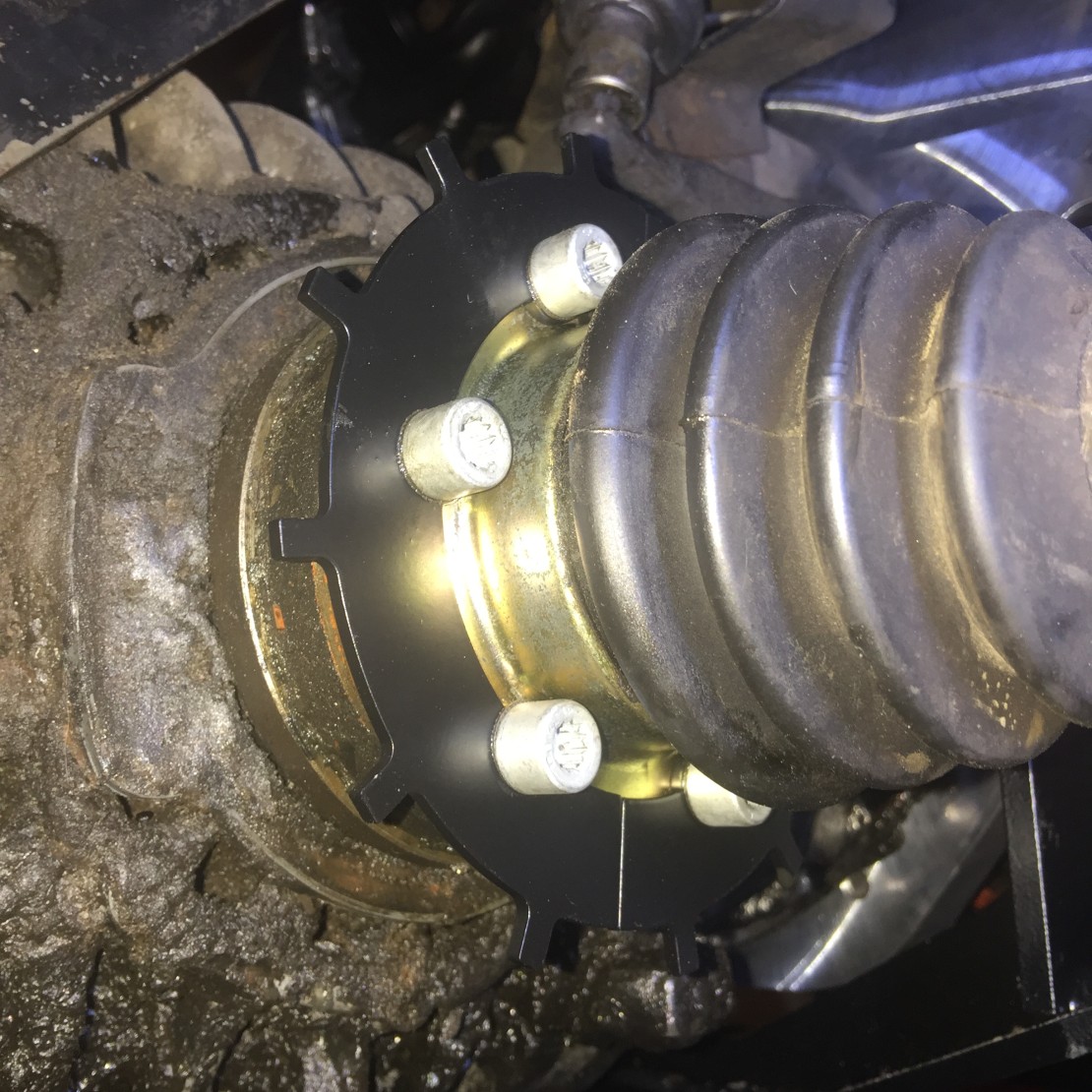
Speed Sensor
This is way "out of order" from the manual, but if I had to do it again, I would install the new Bostig speed sensor at this time. Otherwise, you end up attaching the CVs as part of the mounting process; you then have to come back and undo those same bolts to install the sprocket portion of the speed sensor. (I know what you're thinking, it said to loosely install the bolts. I did this. But at the end of SK-M there was no mention that you'll need to later install the sprocket, so the logical conclusion was to fully torque the CVs once things were in place. Don't make the same mistake!)


One final note on SK-M, make sure the engine is straight in the engine bay! The manual did not explicitly point this out, so sure enough, what can go wrong did go wrong for me.
As mentioned above, it simply said to loosely attach all anchor points (transaxle mount, CV joints, engine cradle, engine mounts) before tightening down. I followed this precisely. I then tightened everything down and finally drilled the two new bolt holes. Little did I know, you can still end up with a crooked engine doing this, doh! With having multiple existing anchor points (cradle mounts, trans mount, and CVs) that were seemingly non-negotiable, I never imagined it could turn out so crooked.
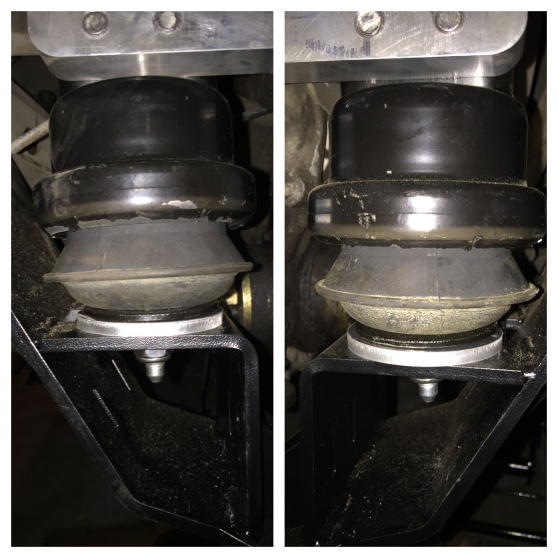
As you can see in the first pic below, I think I was off by almost a full inch from side-to-side the first time. The second pic is 2.5 hours later after I redid the whole process. This was fixable by loosening all of the anchor points and fully removing the two new bolts I drilled holes for. You can then shove/push/kick the whole assembly until it's nice and straight. Re-drilled two more new holes and re-torqued everything and I was finally good to go.


I think the biggest cause of this crookedness was due to the above mentioned use of the non-stock transmission bolt holes. It explains everything, frankly. Since I re-installed two-ish inches to the left of the old holes, the whole thing now pointed to the left. Thankfully, moving it back to the original holes was much less involved. Besides the front mounting bolts, all I needed to loosen were the two engine mount nuts (one on each side). This gave me just enough wiggle room to shove it back to the original holes. Problem solved! No more weird shifting.
Long story short, you will save yourself a TON of grief by making sure that:
You reuse the original bolt holes for the transmission mount.
You make sure the engine is absolutely straight in the engine compartment before you fully secure anything.
Finally, the end of SK-M. Technically the new motor is now in the van!
SK-W (Wiring)
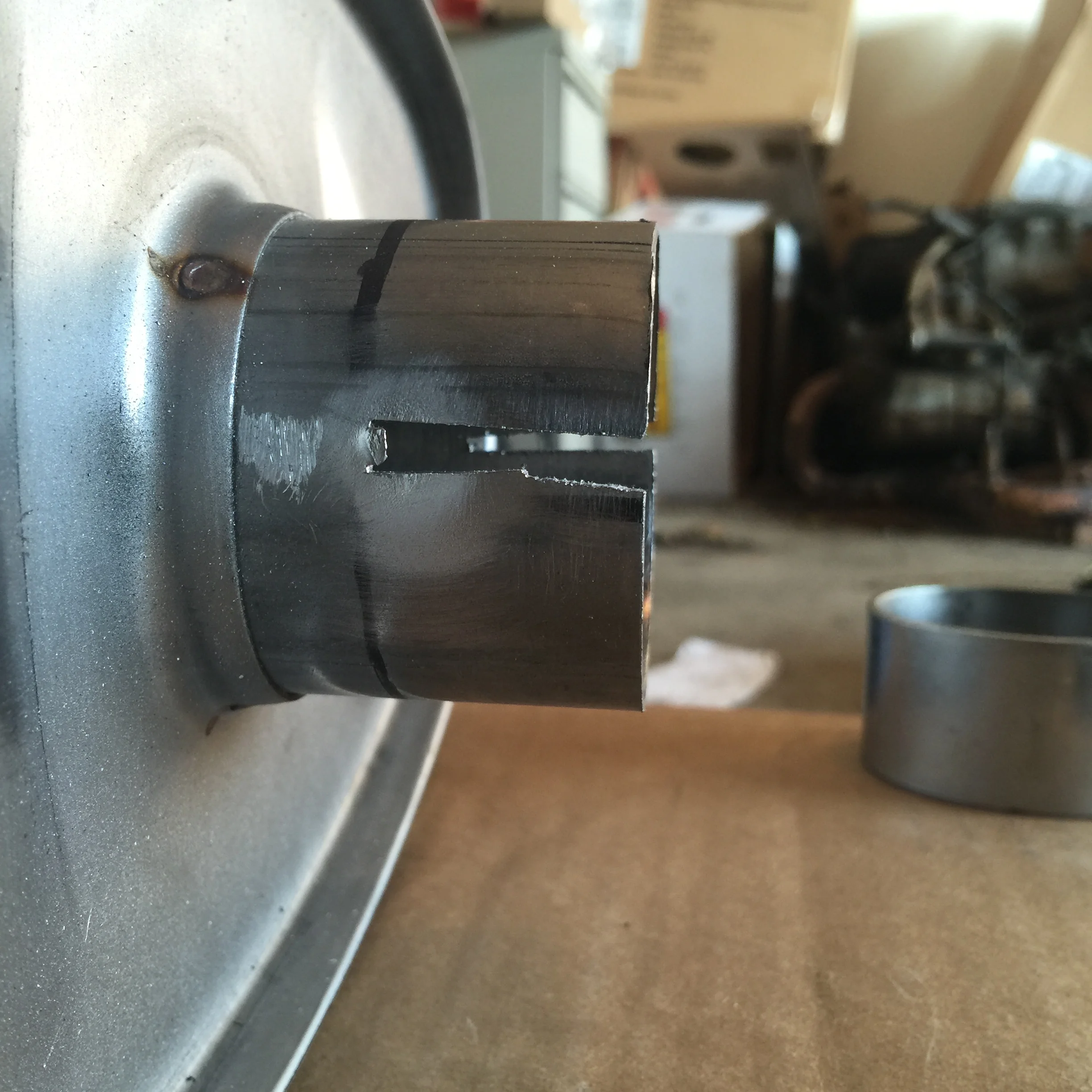
SK-W (Wiring) was next on the list. Keep in mind this is a 1985 Westy Weekender 2WD, so no kitchen, no 4WD, no rear gas tank, etc. (Installation will be slightly different for each type of van.) This also means I needed a 2-inch hole saw to cut an access port for the new harness.
I "hummed and hawed" for quite some time over where exactly to cut the hole. My main concern was if I would run into something on the back side of the hole, i.e, in the engine compartment. There was a dimple in the metal that worked great as a reference point. I mocked things up best I could and finally settled on this location. I realized later there is plenty of slack in the harness to mount it just about anywhere.


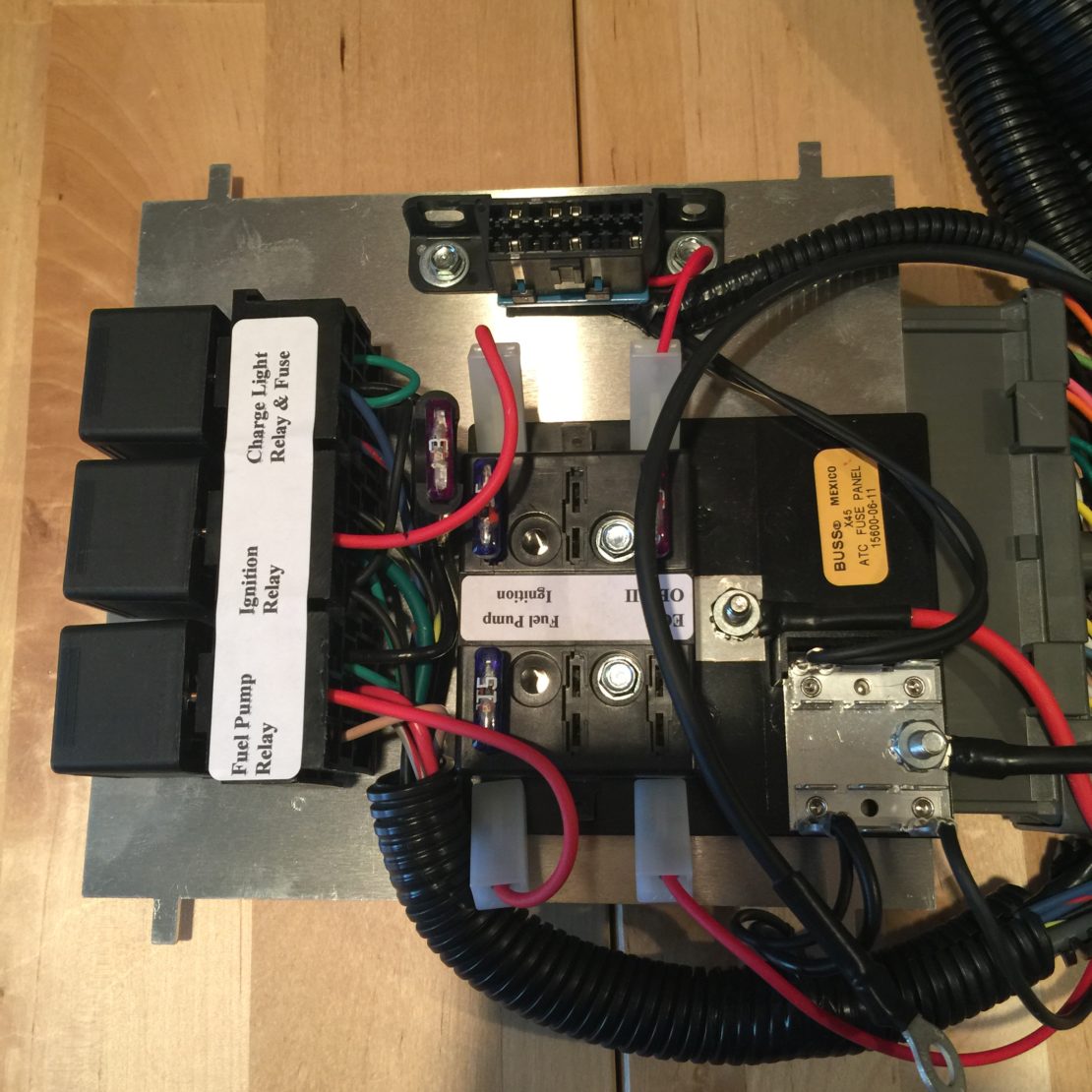
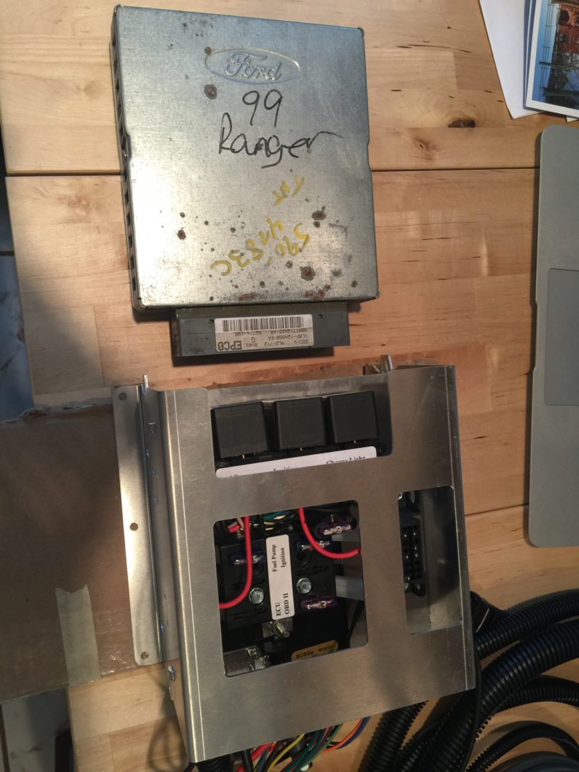
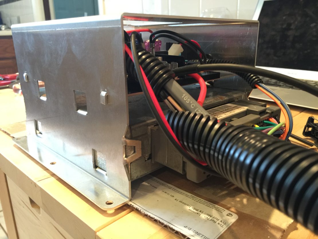
ECU Bracket
Not much to say for the mounting of the harness and ECU within the bracket, Bostig's video pretty much nails it if you really want to see the nitty-gritty details. You'll need a long phillips-head bit to screw the unit in place. This 6-inch bit along with this bit magnet worked perfect.


Fuel Lines
Running new fuel lines for the Zetec was a piece of cake. Apparently it was so simple I forgot to take pictures of the process, ha! There are simply two lines; a supply line coming from the fuel pump and a return line going back to the gas tank.
If you've ever replaced the original Waterboxer's fuel lines you will laugh at how simple the Zetec is. No extra "T's", no extra fuel rail pieces, and no hazardous firewall connection to deal with. Just route them in a safe manner and you're good to go.
While we're on the topic of fuel lines, now is a convenient time to hookup the power to the fuel pump.
Fuel System
At the same time as the fuel lines, you address some other items like the EGR block-off, a new fuel rail inlet, sealing off some extra intake nipples, and a new fuel pressure regulator. All of these are simple. Only tip I have is to route and connect the fuel hose to the fuel pressure regulator before installing the regulator itself. It seemed to be a tight fit for my hands to get in there.


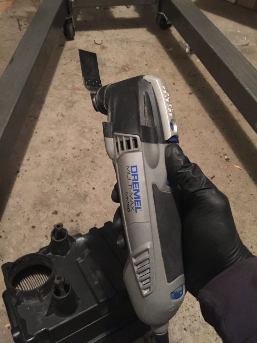
Air Box
The air box modification was pretty straightforward. Unfortunately, it was the one time that my planning ahead got the best of me. I downloaded the original cut template at the beginning of the conversion in September. I didn't do the mod until December. While writing this post I noticed the instructions were updated in October which makes the cutting much more simple, doh! What I did still works fine, but of course something like that would happen to me, ha!
About the only thing I had a question on was where the "resonator" was located. It's the smaller section on the end of the air box. Definitely keep this piece as it helps keep things quiet!
Also, soak the four bolts on the air box in PB Blaster (or something similar) as soon as you can, and apply multiple times. All of mine were a bear to remove, and one of them had to be drilled out, breaking three drill bits in the process! Ridiculous. An oscillating saw worked perfectly to cut the legs off; was fast and gave a nice, clean cut.


Cooling System
This is probably the most involved Bostig-part of the conversion. This section was also the most wonky to navigate in the manual; the steps were out of order in my opinion. It had you cutting hoses before you knew the exact length for certain things. If you ask me, the best workflow would be:
Swap front hoses at radiator
Install fill tower
Install overflow bottle
Cut and install hoses - little to no measuring required
Swap Front Hoses
Here's swapping the hoses up front. You have to drop the spare tire to gain access. Simple, albeit, slightly awkward and annoying. I reused my hoses, I'm sure new ones would have slid off and on much easier.


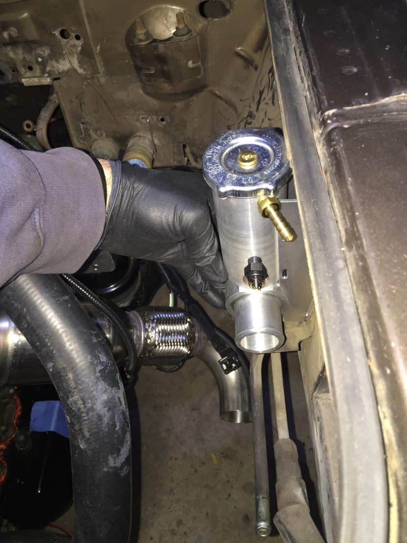
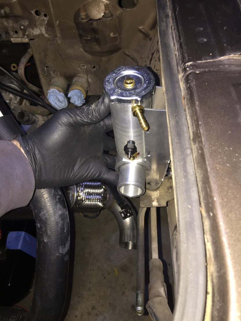
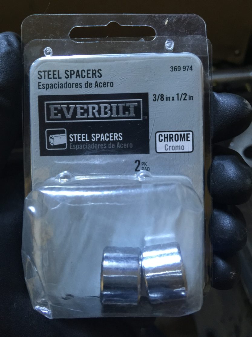
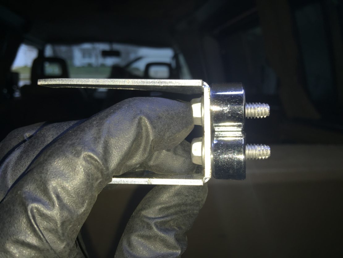
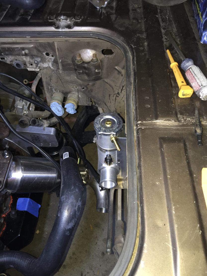
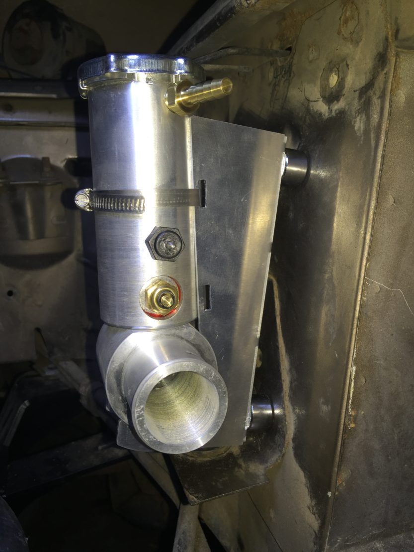
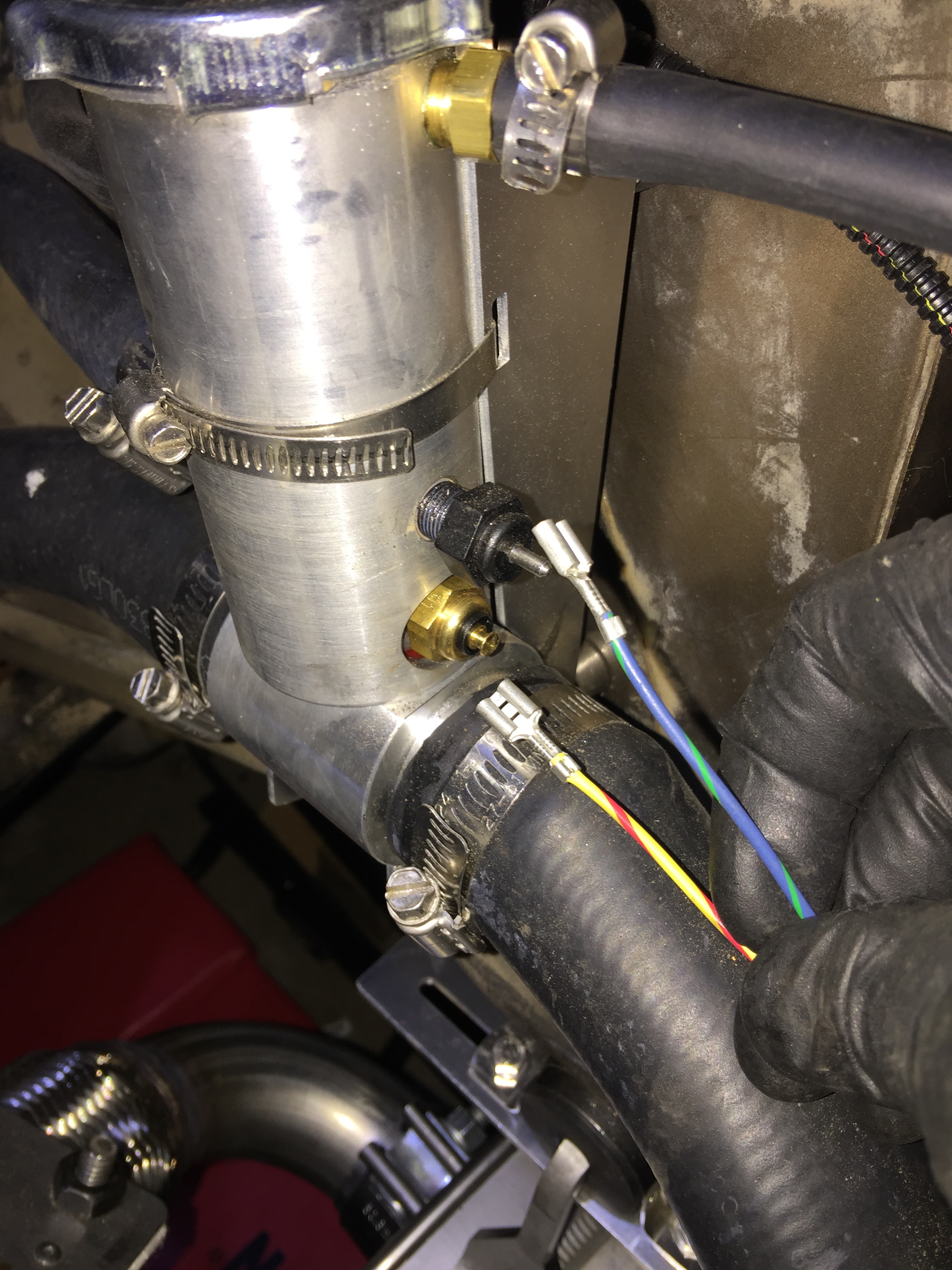
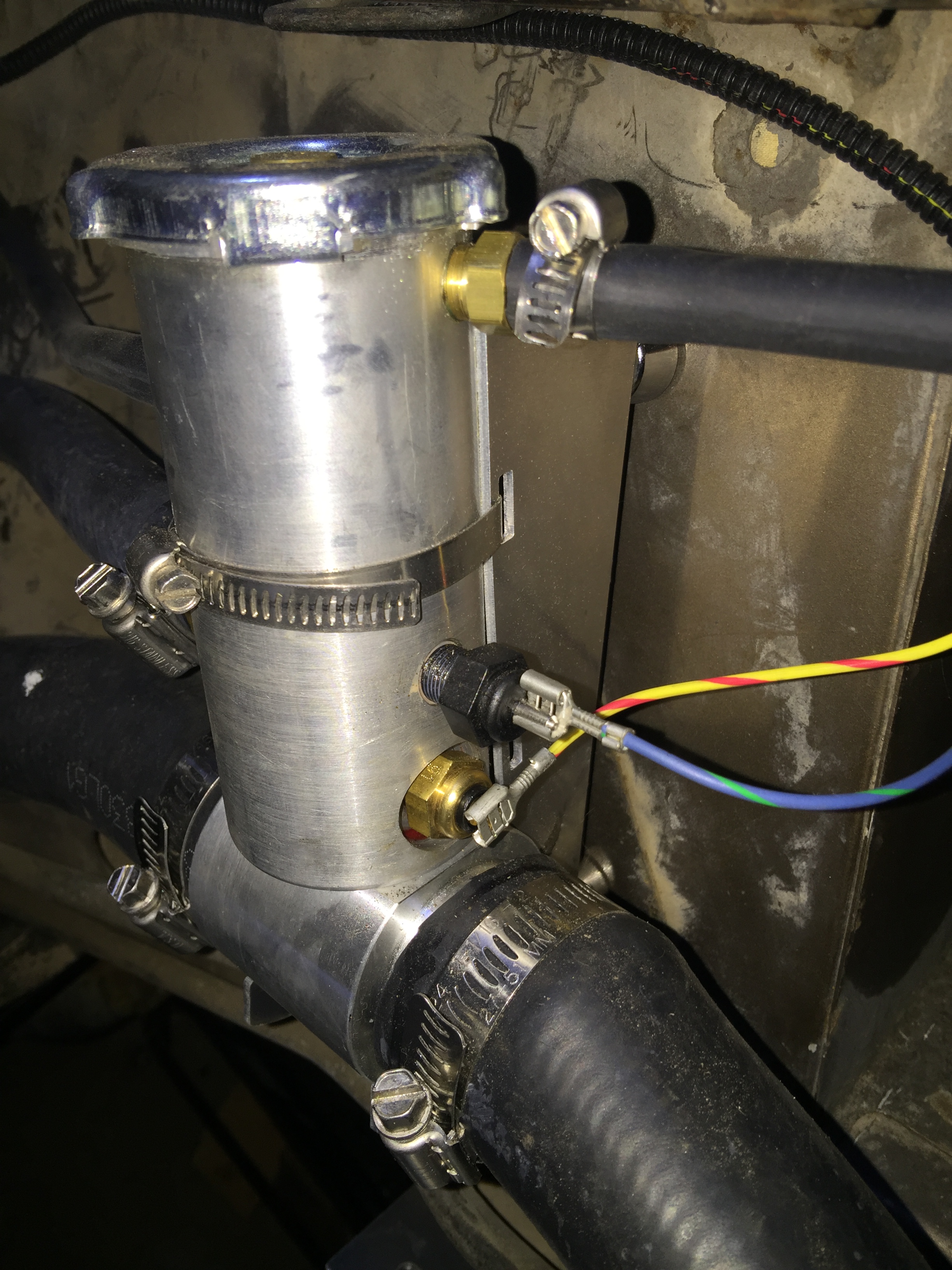
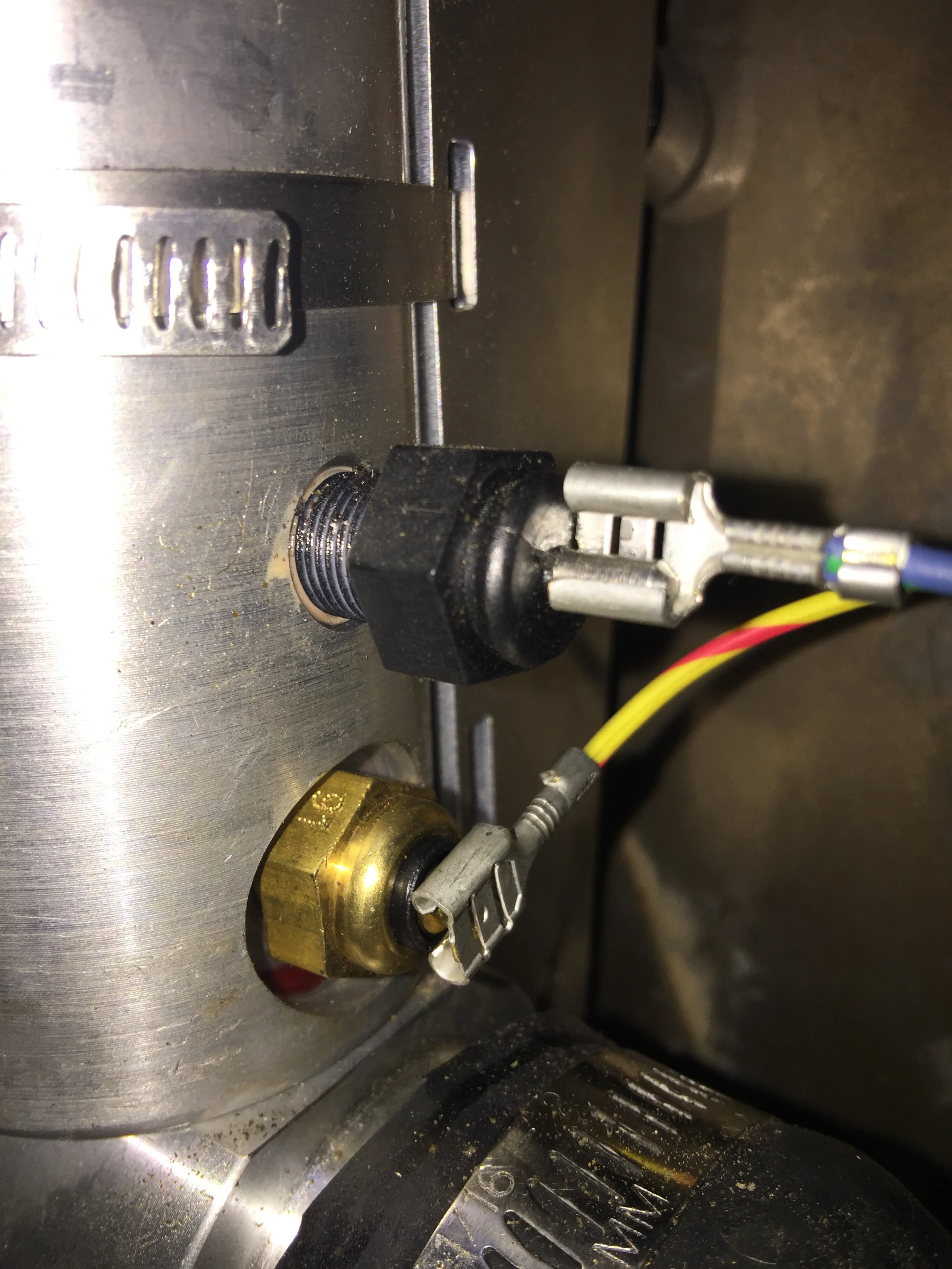
Coolant Fill Tower
I had previously seen people mention that the fill tower is a little tough to access once installed. I took their advice and installed some spacers that I picked up at Home Depot for a few dollars. This moved the tower away from the wall and out from under the overhang. For once, everything worked perfectly! Was super simple, looks nice, and I'm glad I did it; can take the cap on and off with zero interference now.
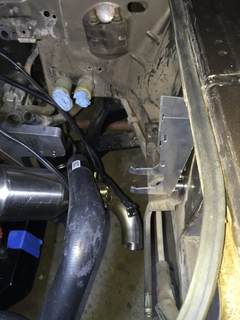


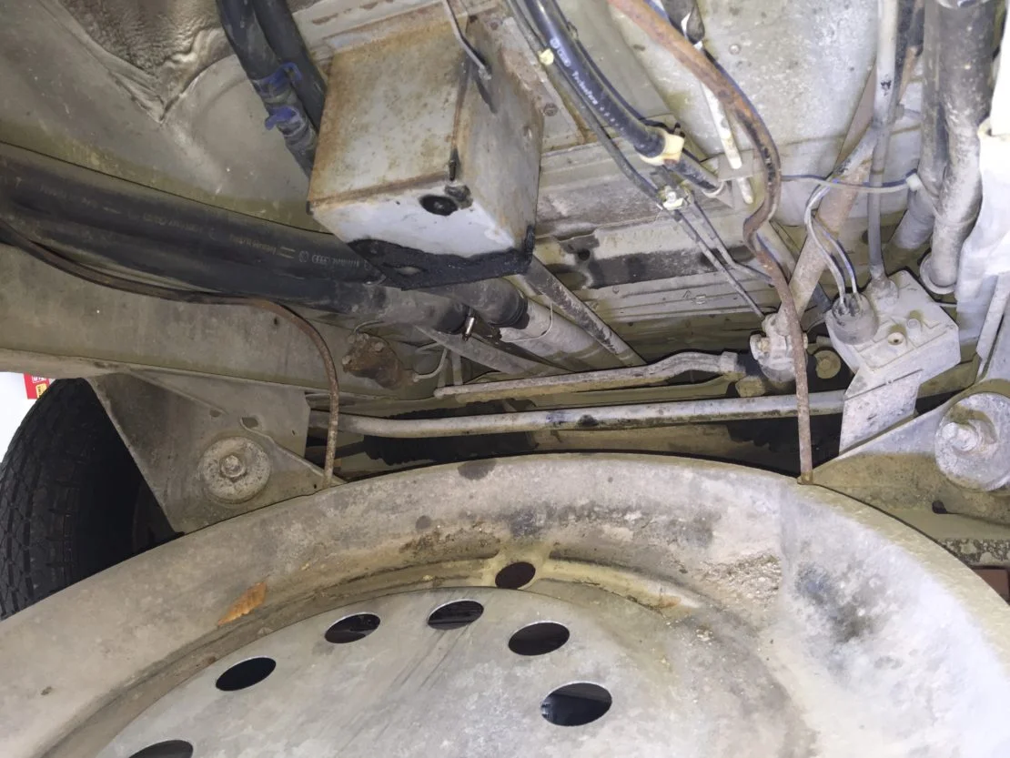
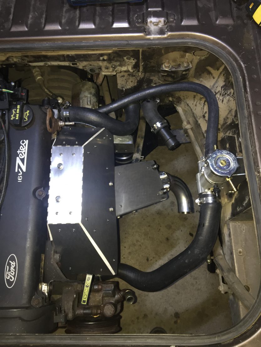
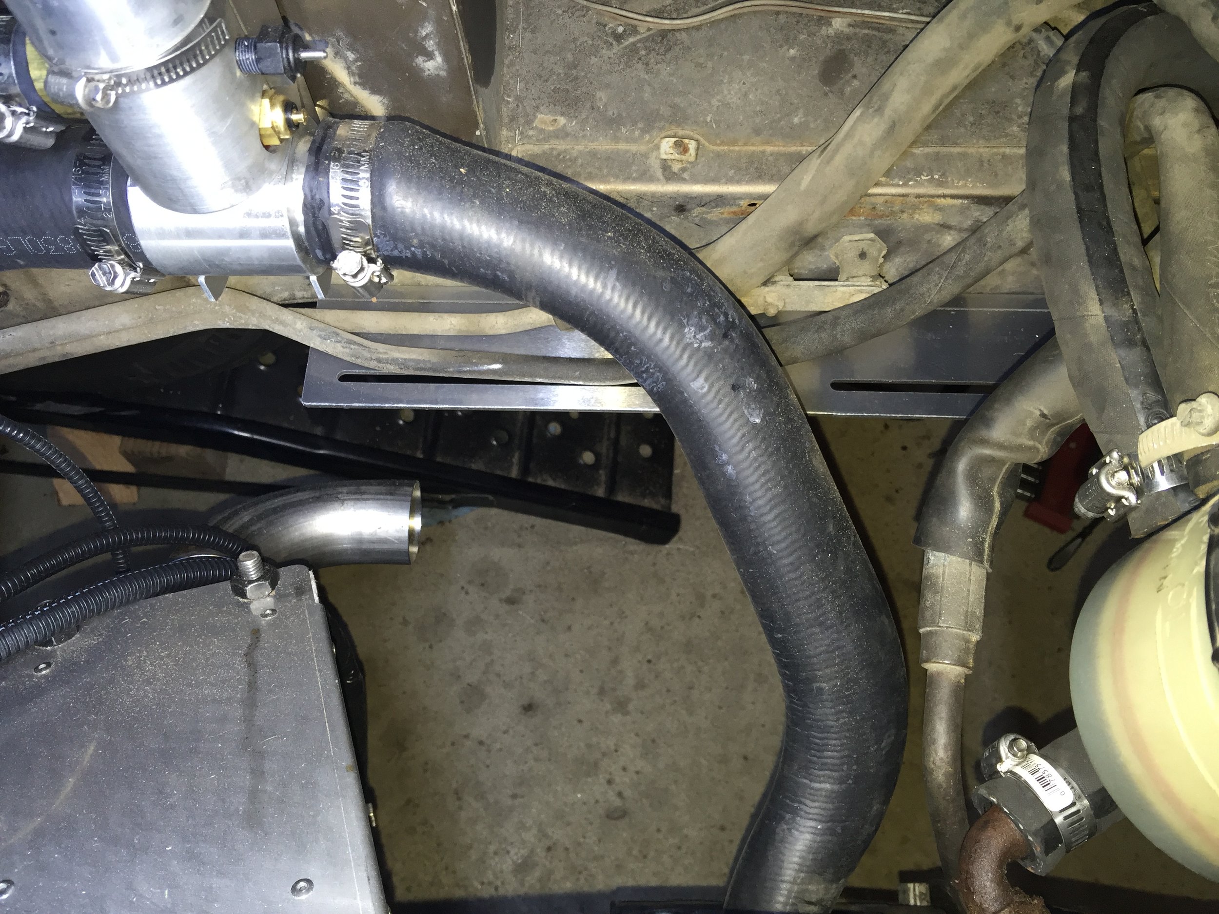
Coolant Overflow Bottle
Apparently I didn't snap a pic of the coolant overflow bottle when I installed it. Here's the closest pic after the fact (bottom left corner):
It's a simple install; just held in place by some sheet meal screws. The main thing here is that it fits in between the air box and the alternator. I installed it by going with the measurements in the manual, which is ultimately fine. However, if I were to do it again I would:
Make sure both the air box and alternator are in place.
Position the overflow bottle to my liking. I would probably put it slightly closer to the alternator. It's kind of a tight fit getting the air box in and out, so another inch or so of space would be nice to have.
Mount the bottle...no measuring required.
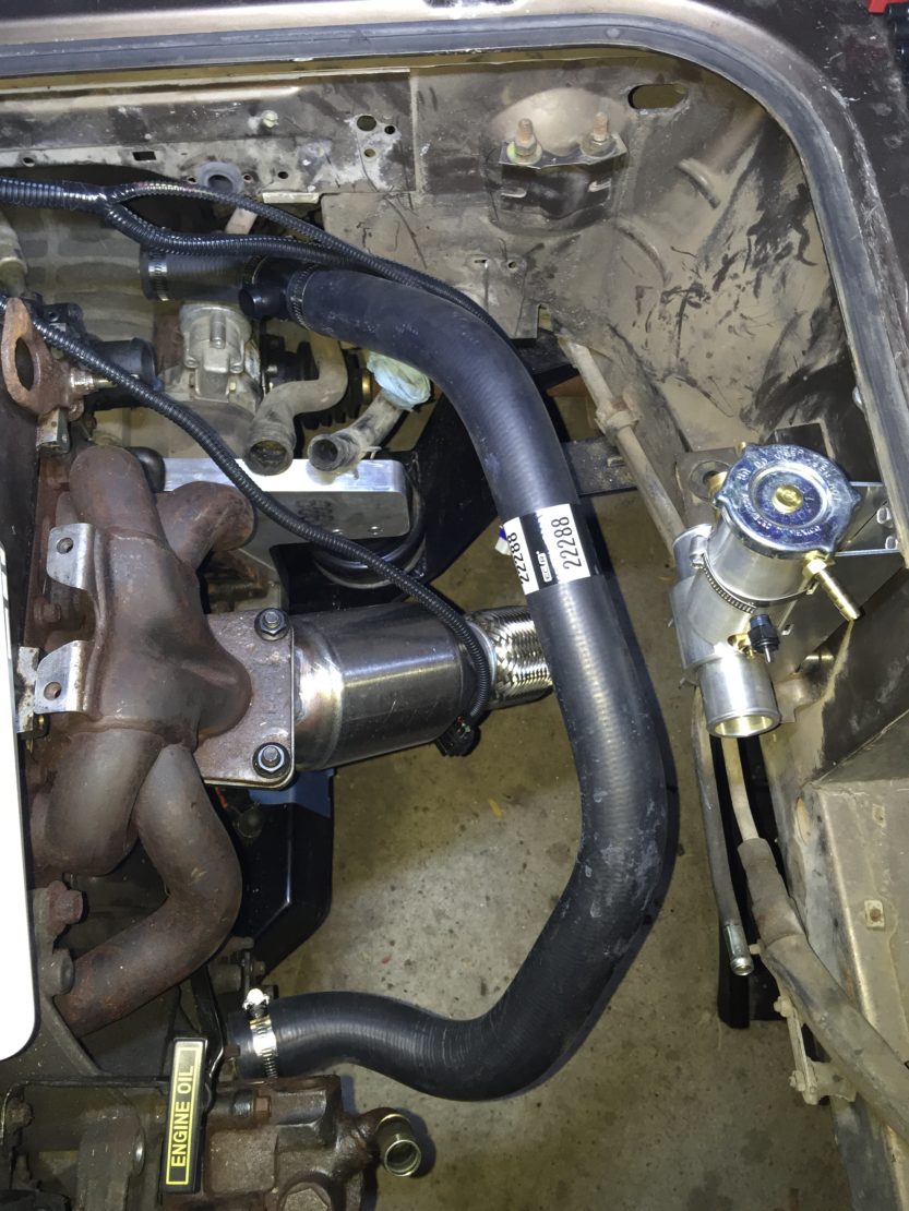
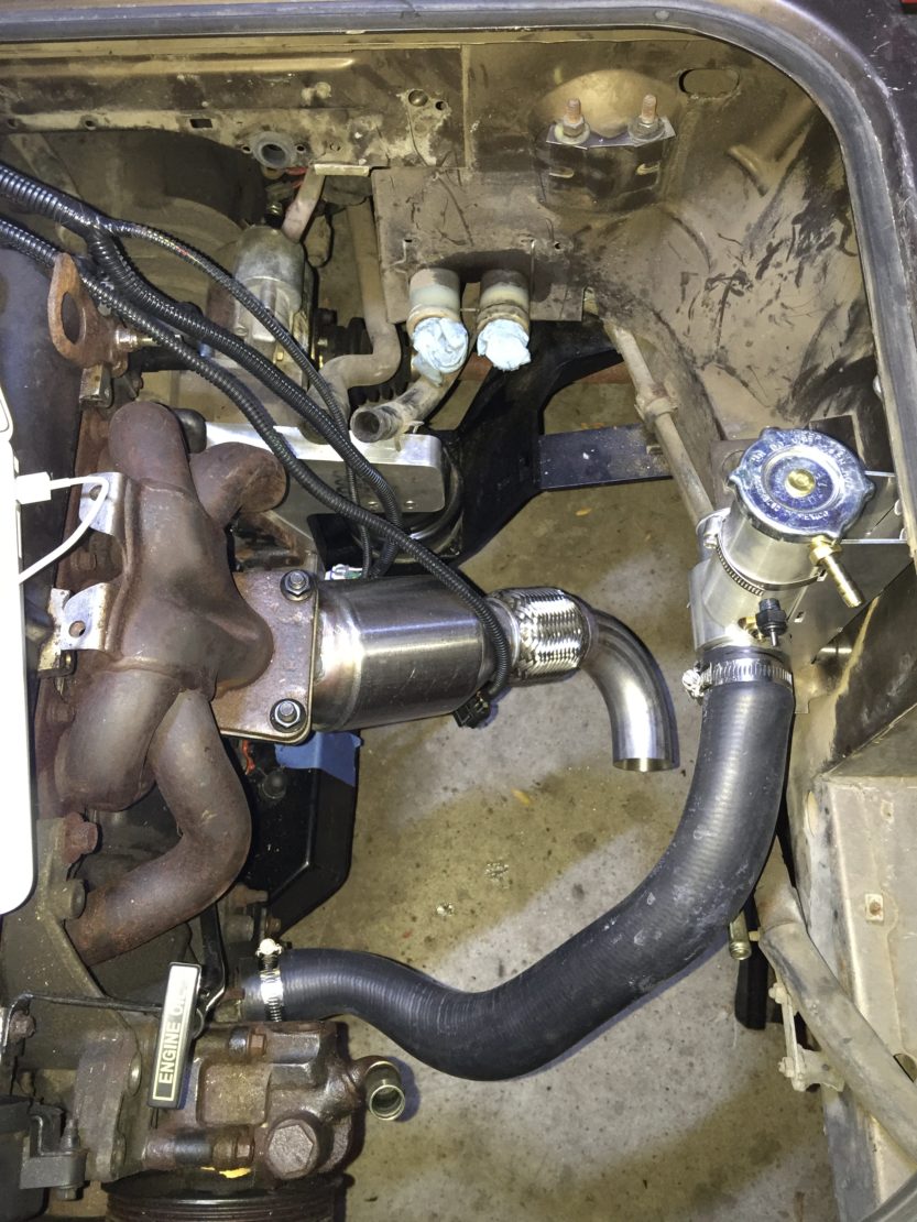
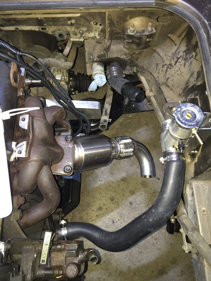
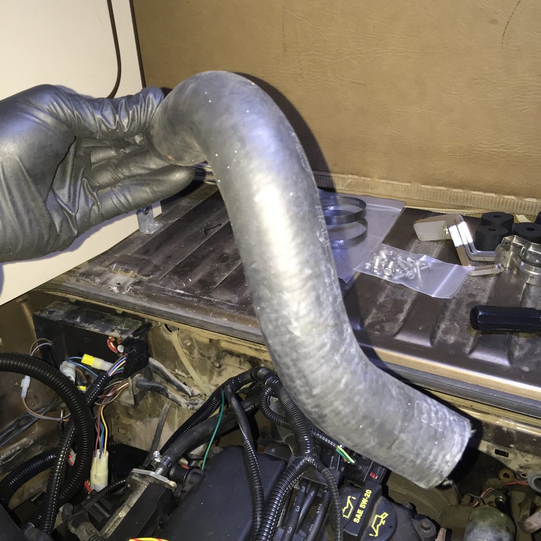
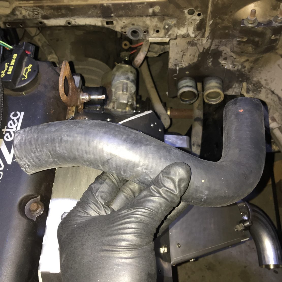
Cut & Install Hoses
With the coolant fill tower and overflow bottle both in place, now you can cut and install the hoses with no guess-work on measurements.

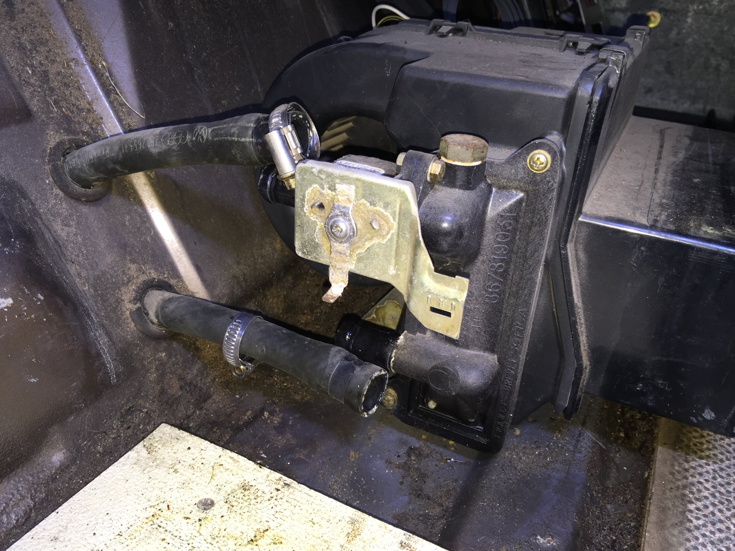
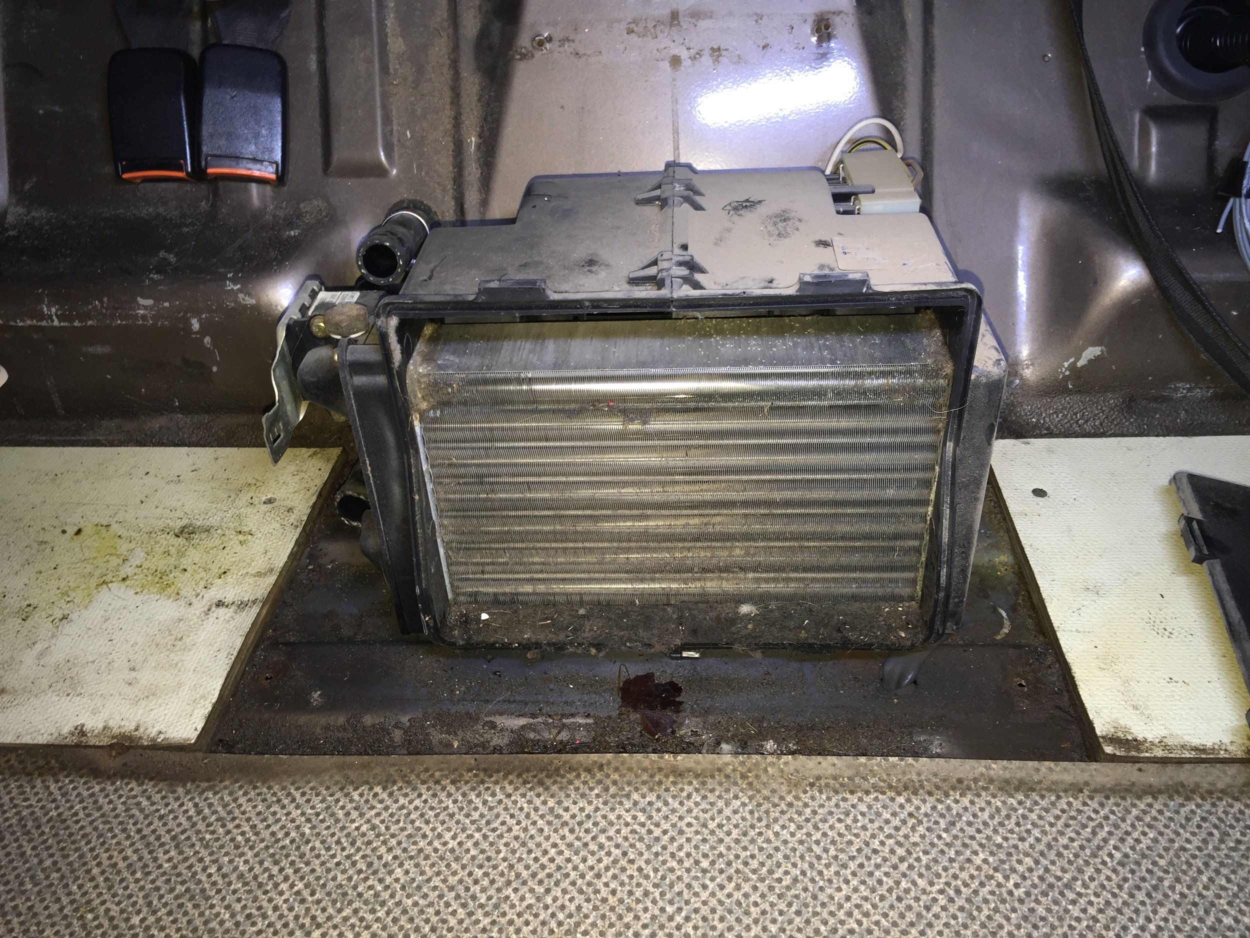
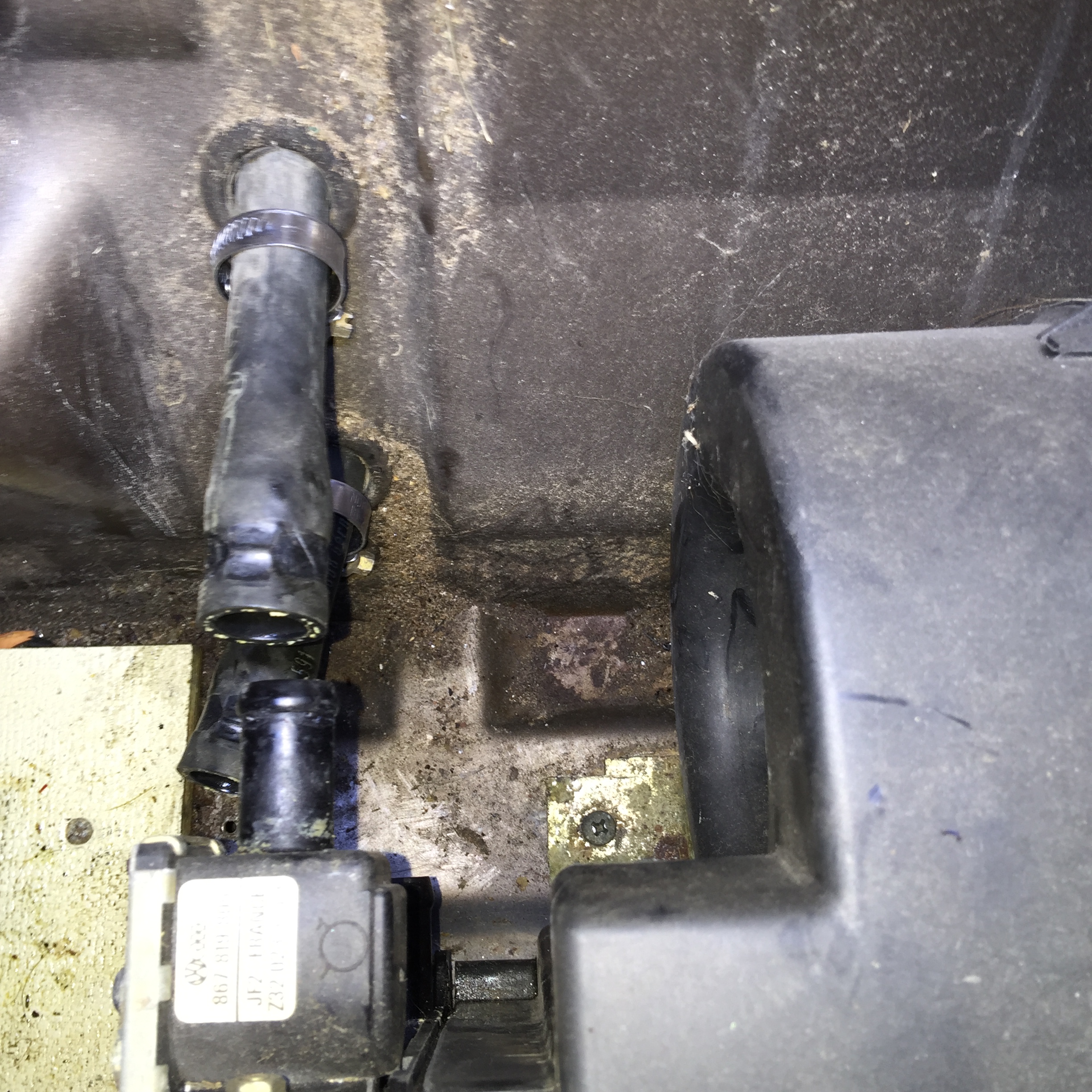
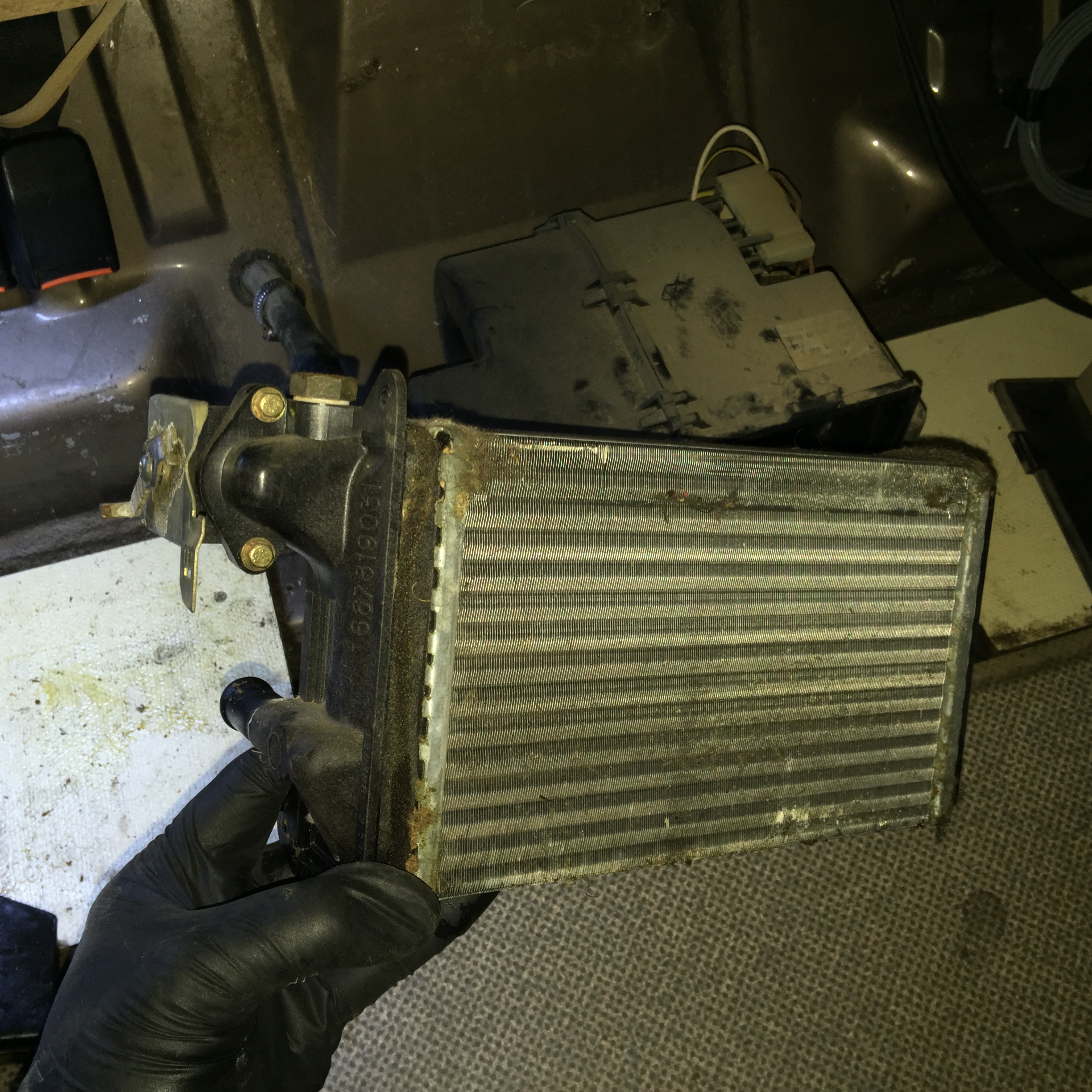
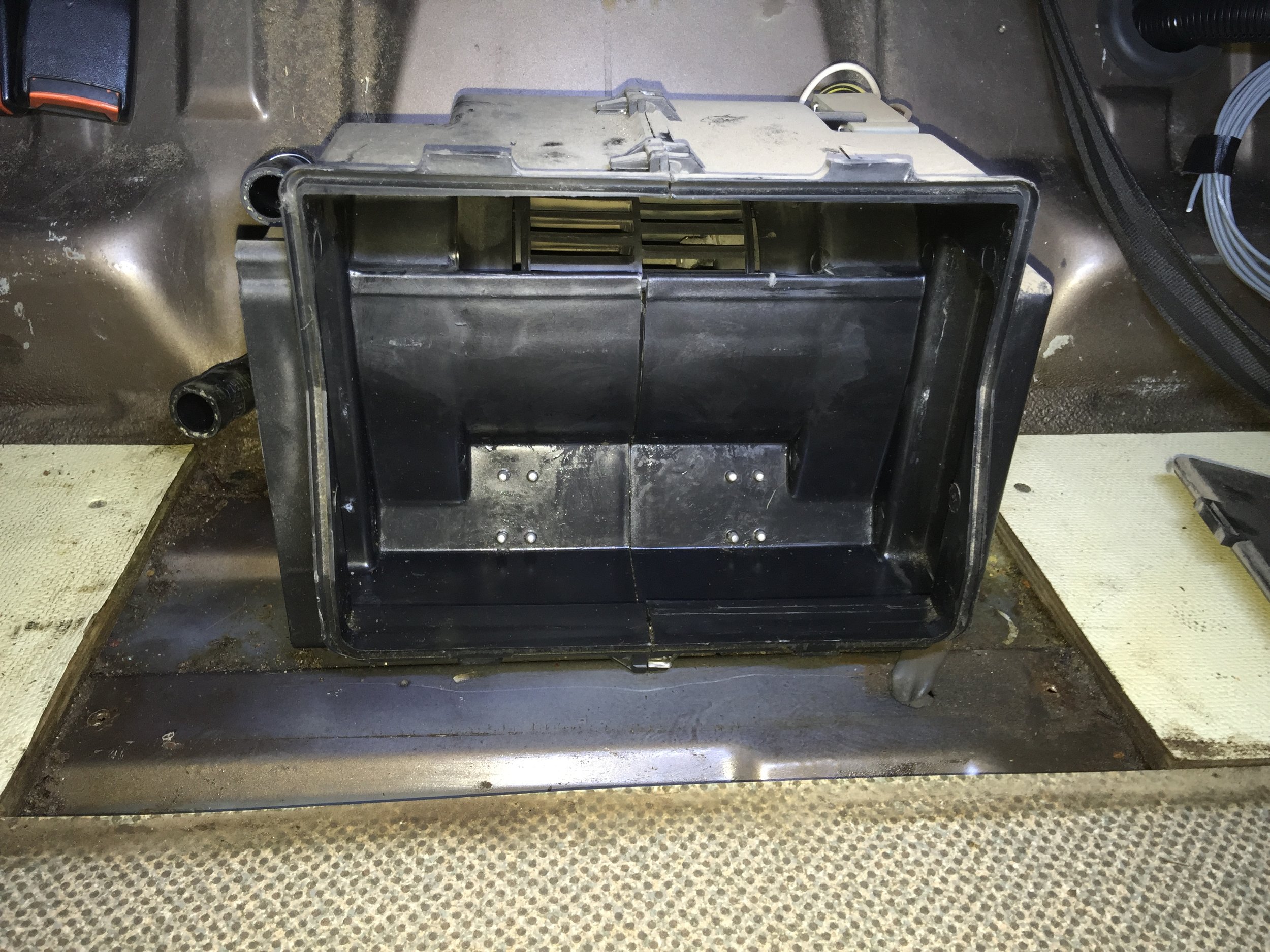
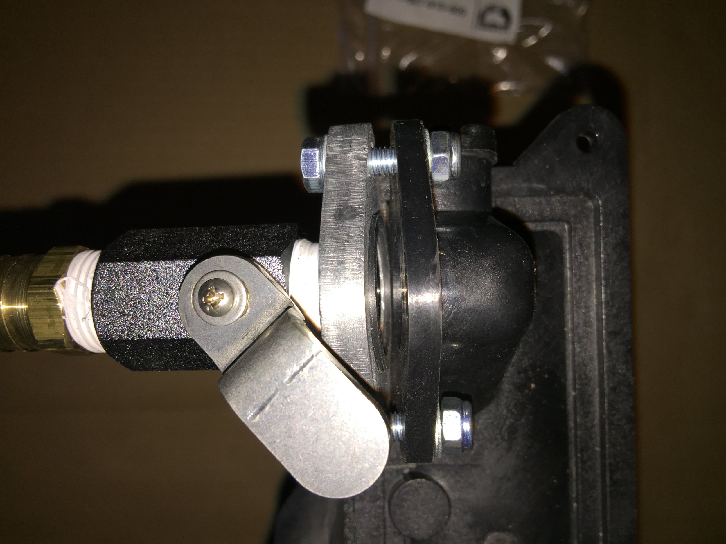
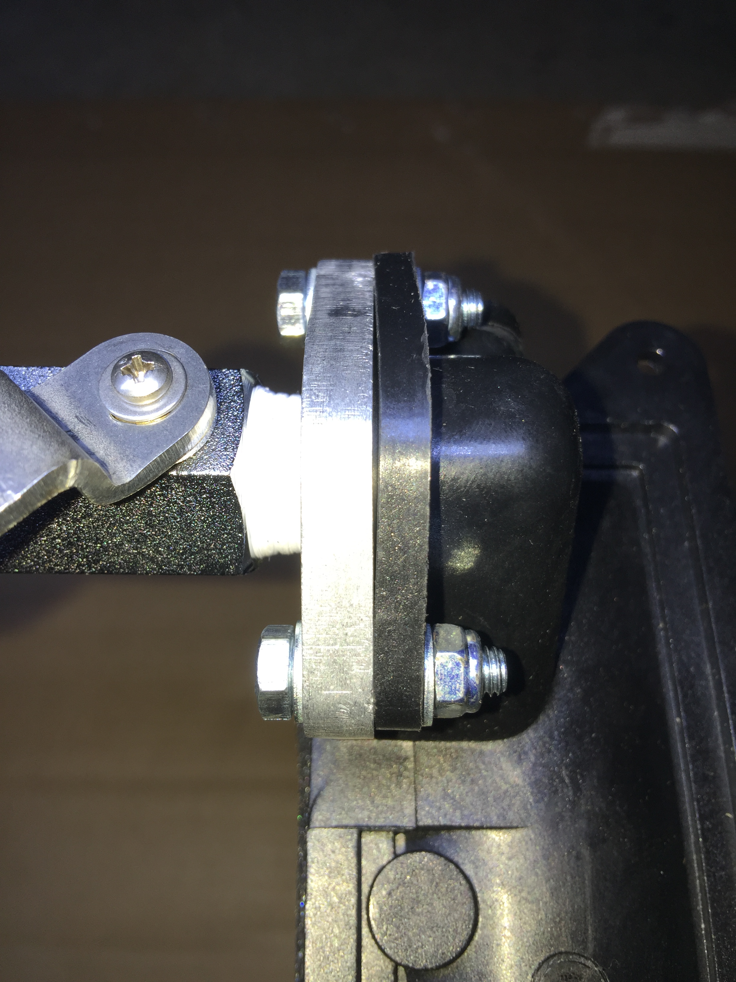
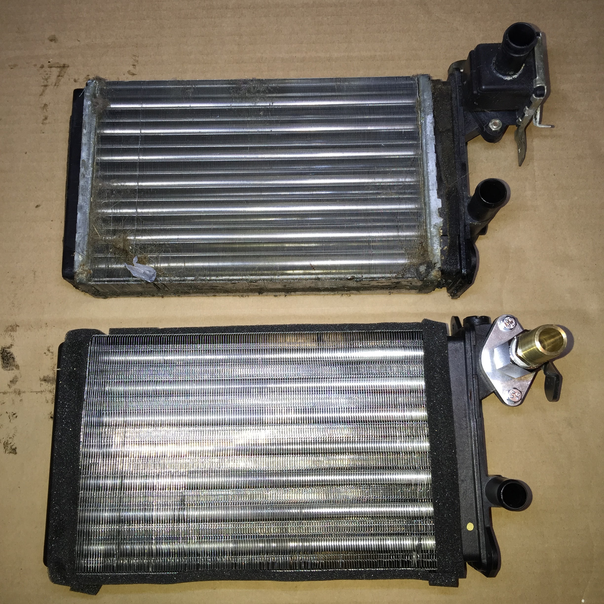
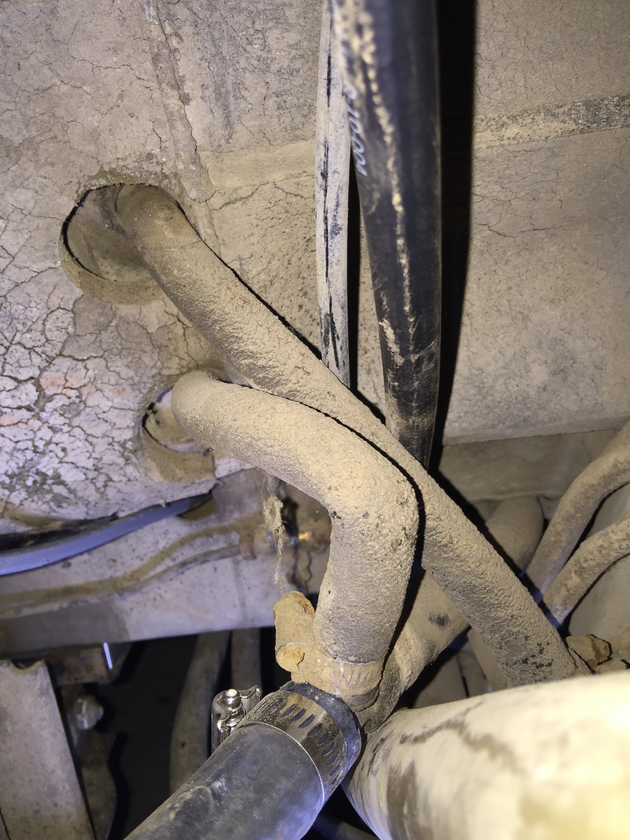
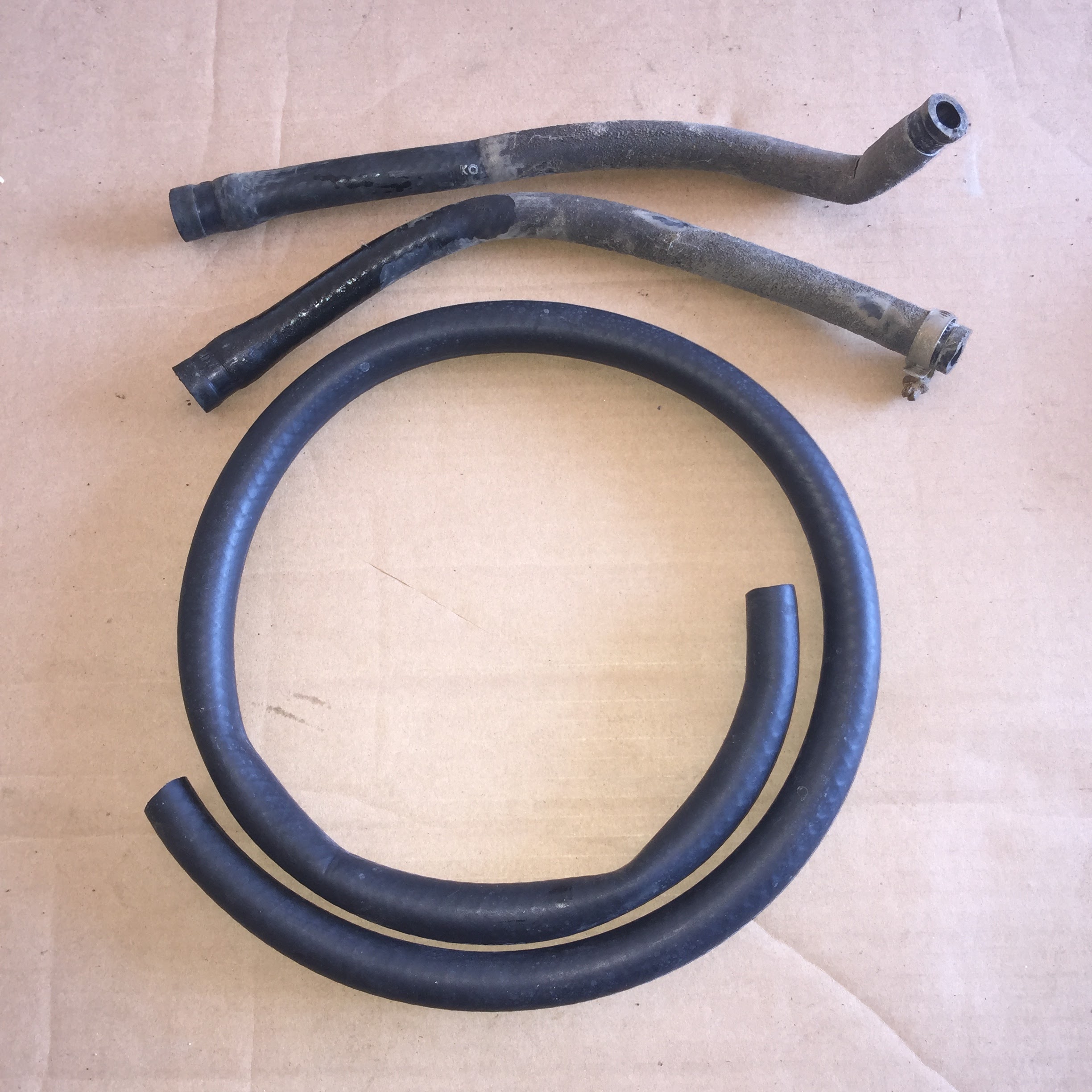
Rear Heater Core & Hoses
Though not officially part of the Bostig conversion, this is also the perfect time to give your rear heater core an overhaul. Ours had been leaking for quite some time so it was a long overdue fix. If you’re still running with the original core and/or valve, you should nip this in the bud while you can, as it’s only a matter of time before it will fail. (It’s usually the valve that leaks the most.)
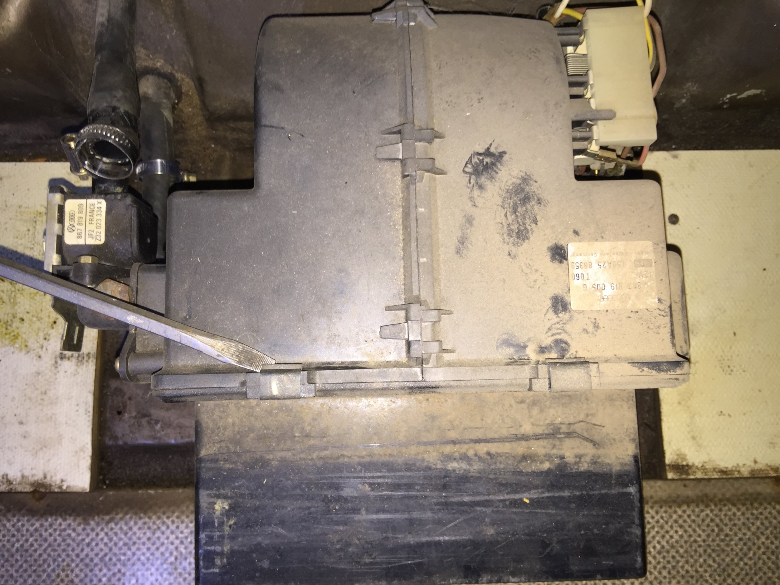
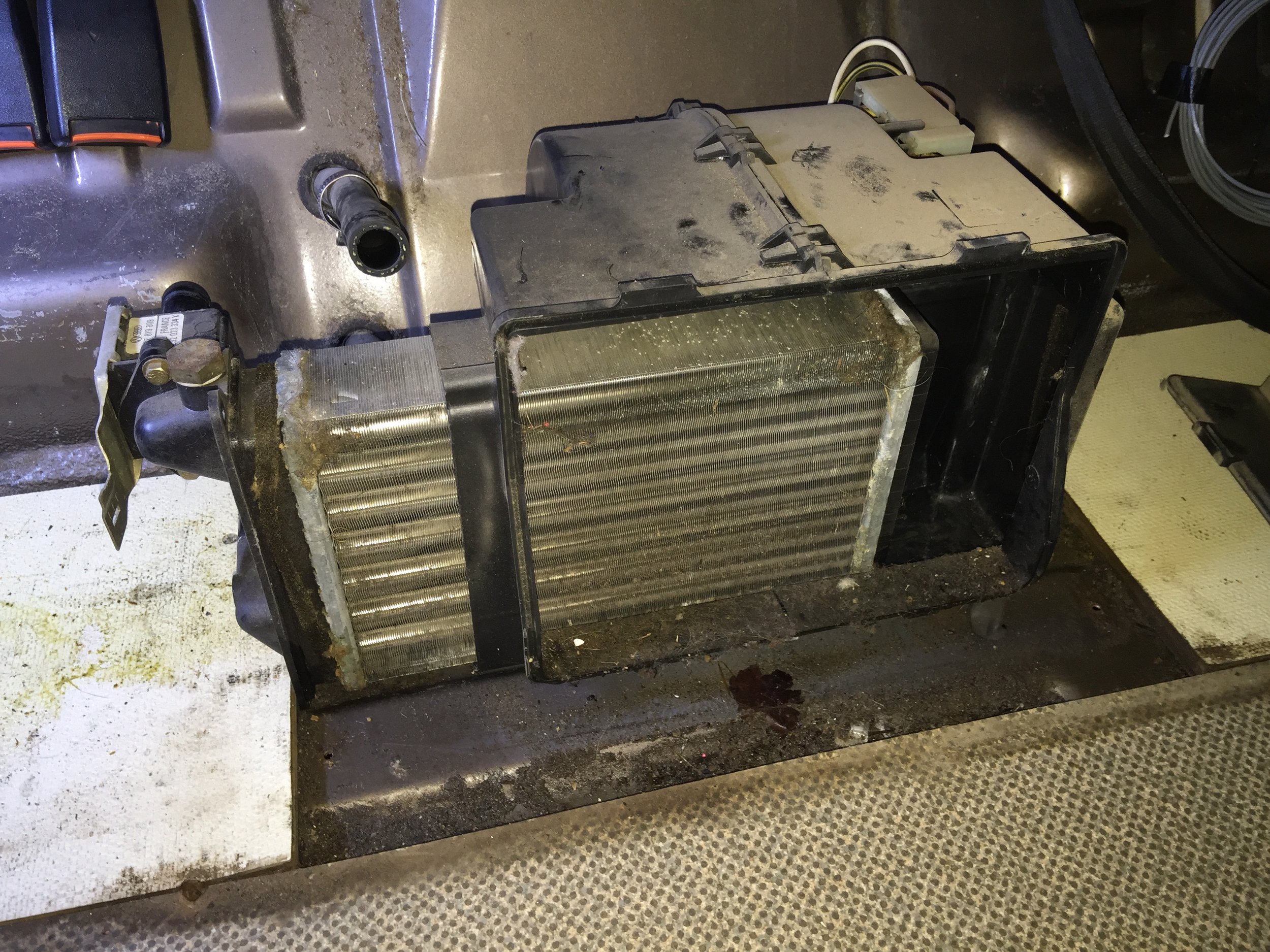
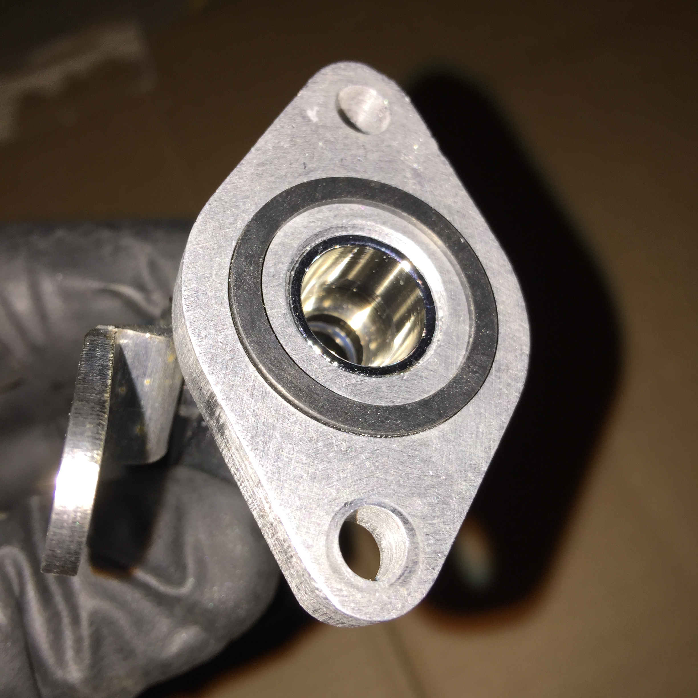
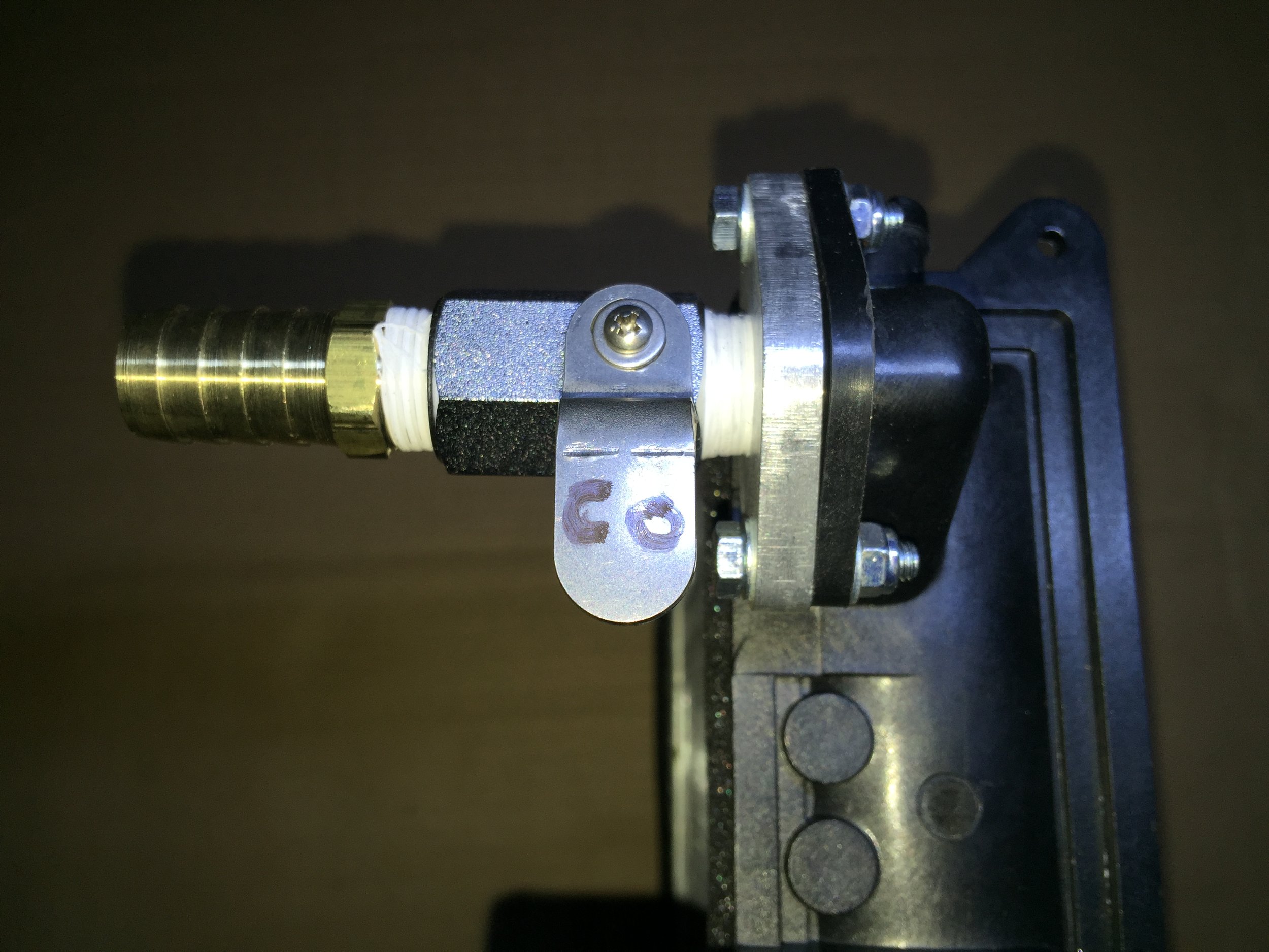
First up, replacing the core and valve:
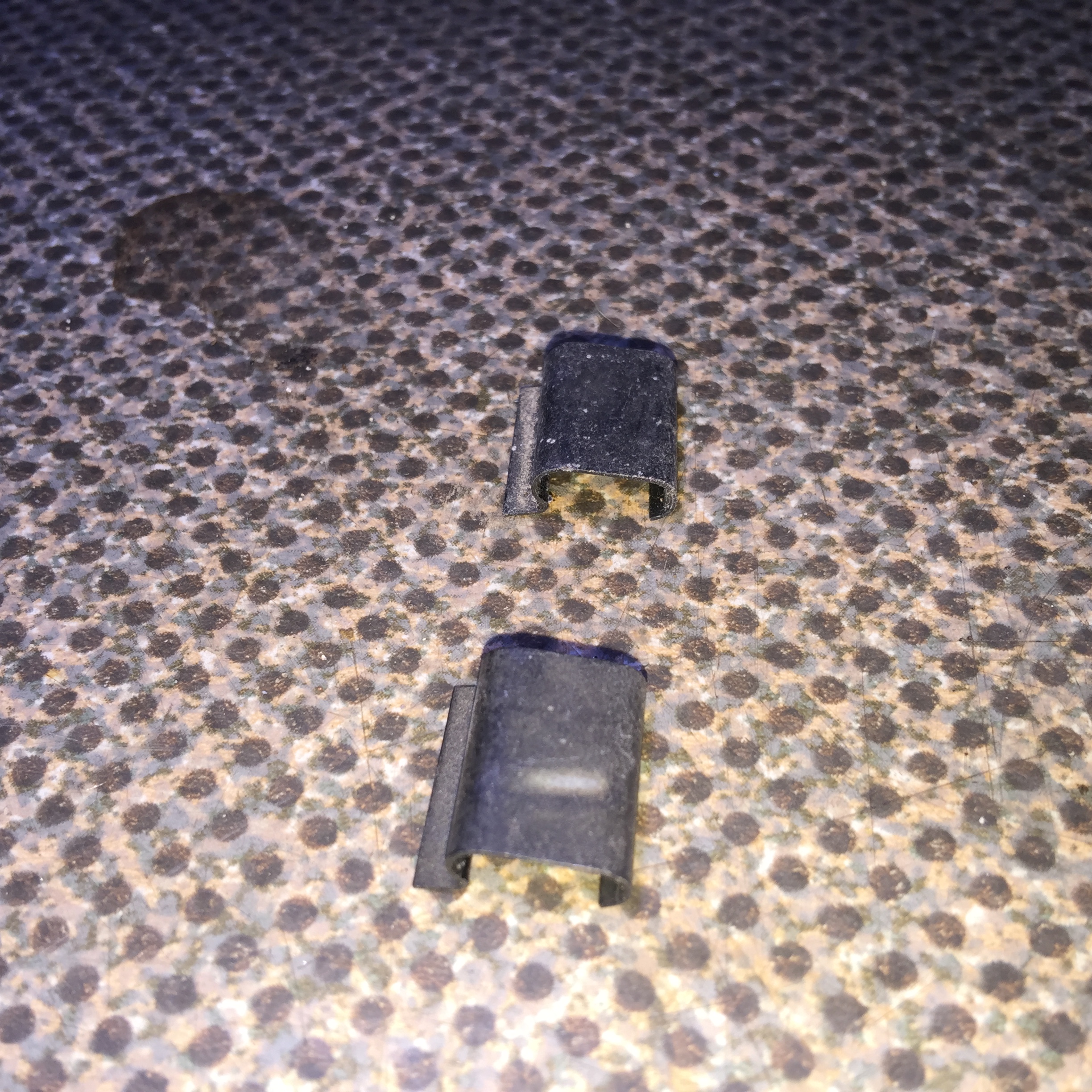
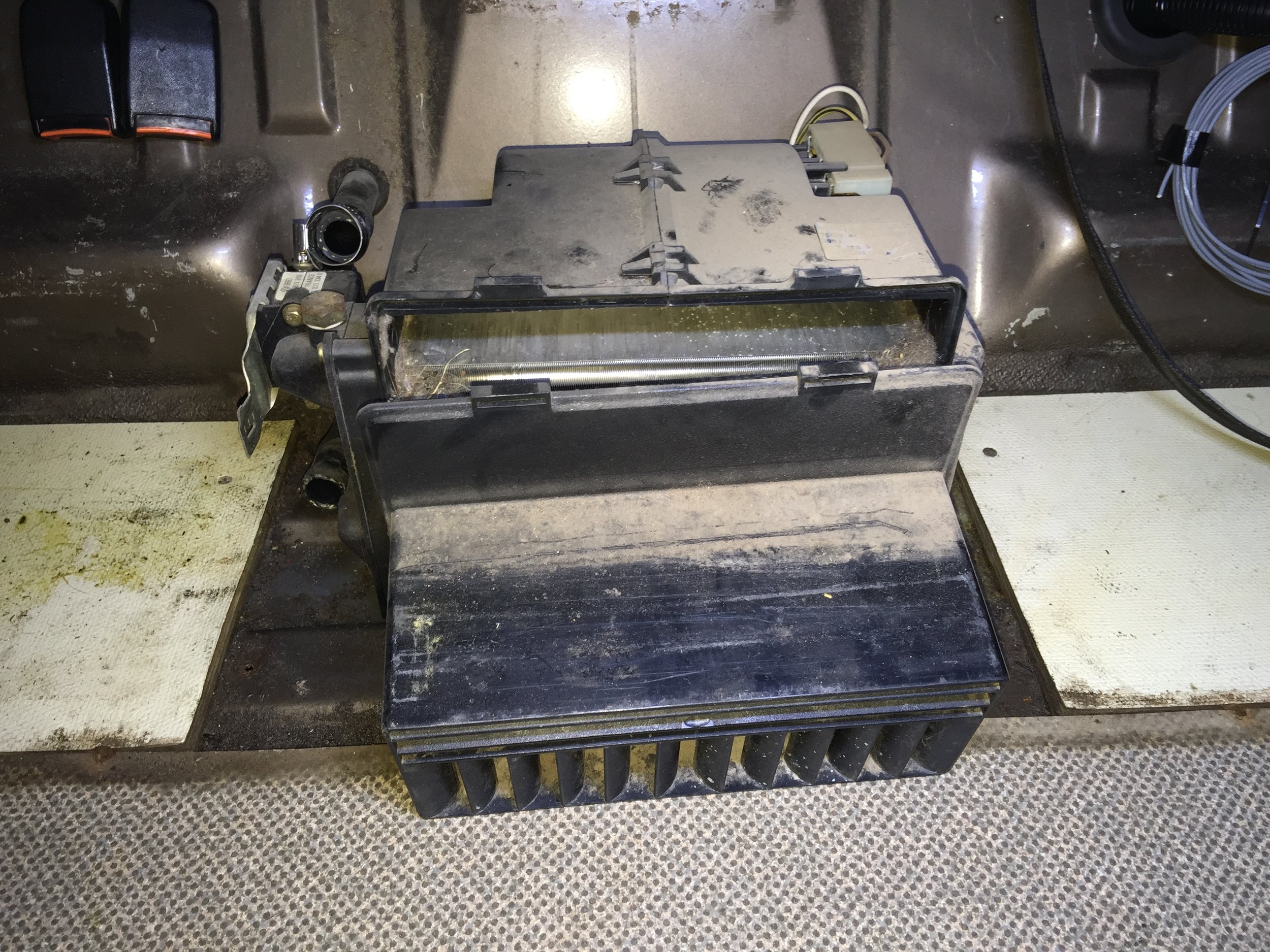
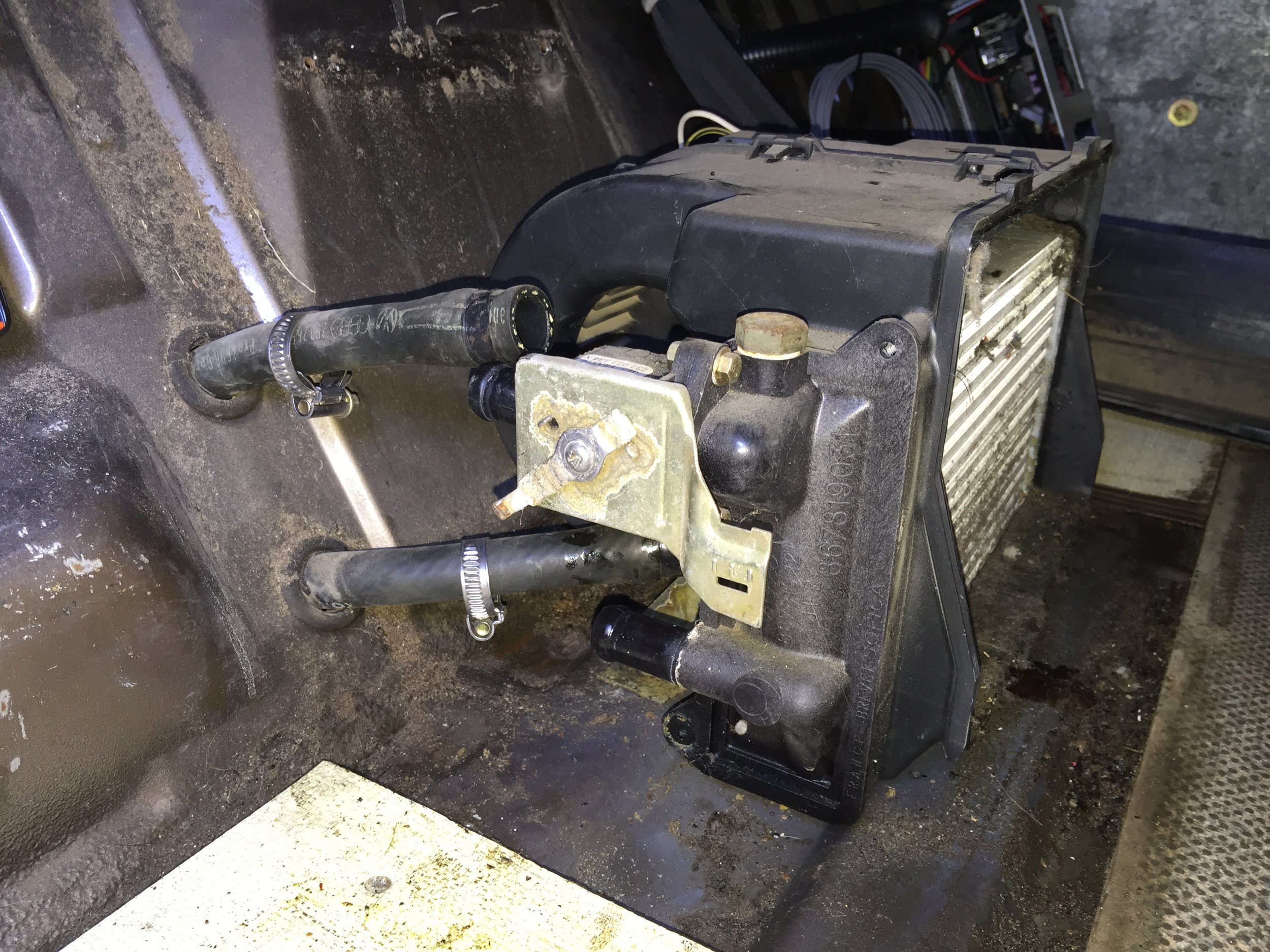
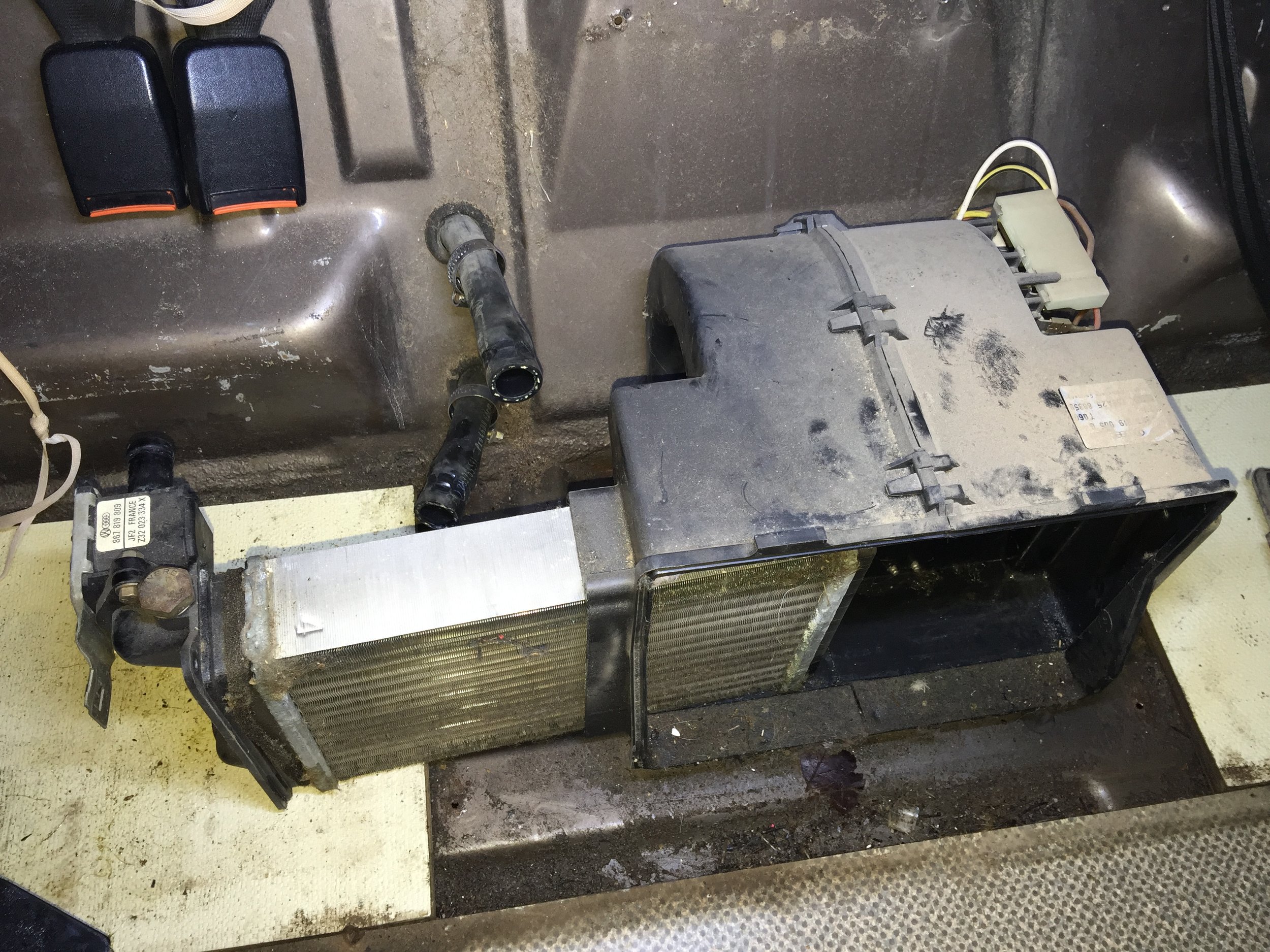
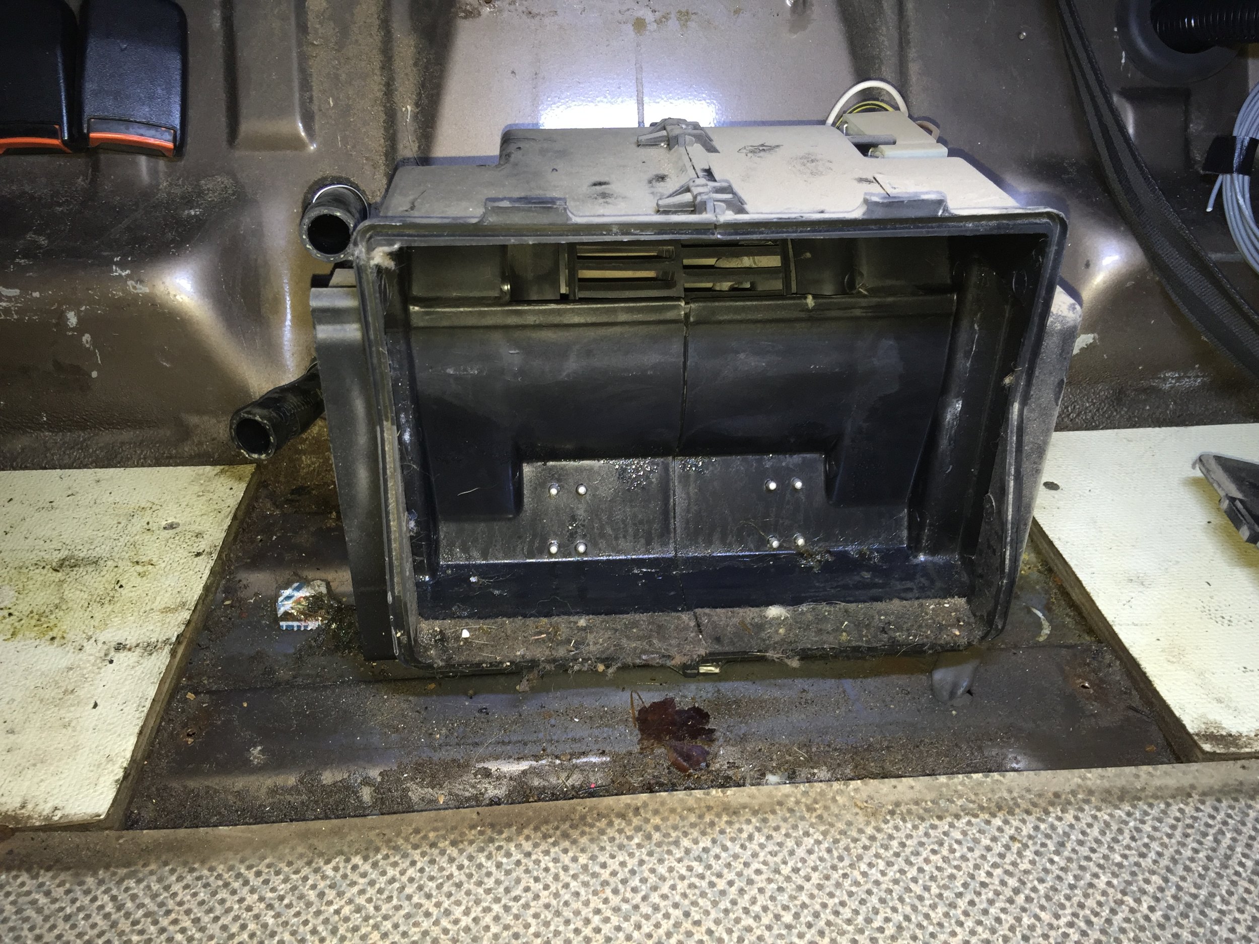
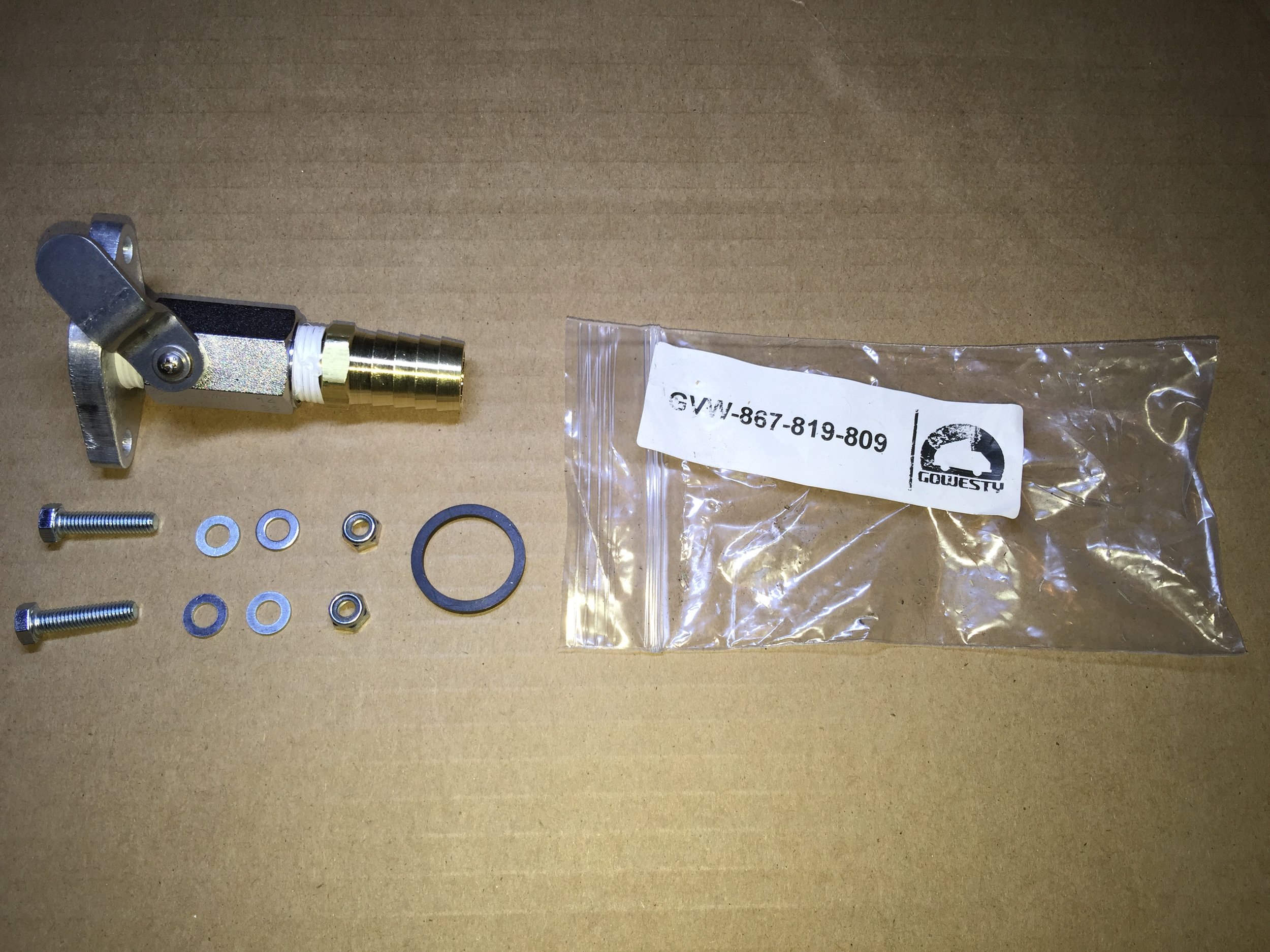
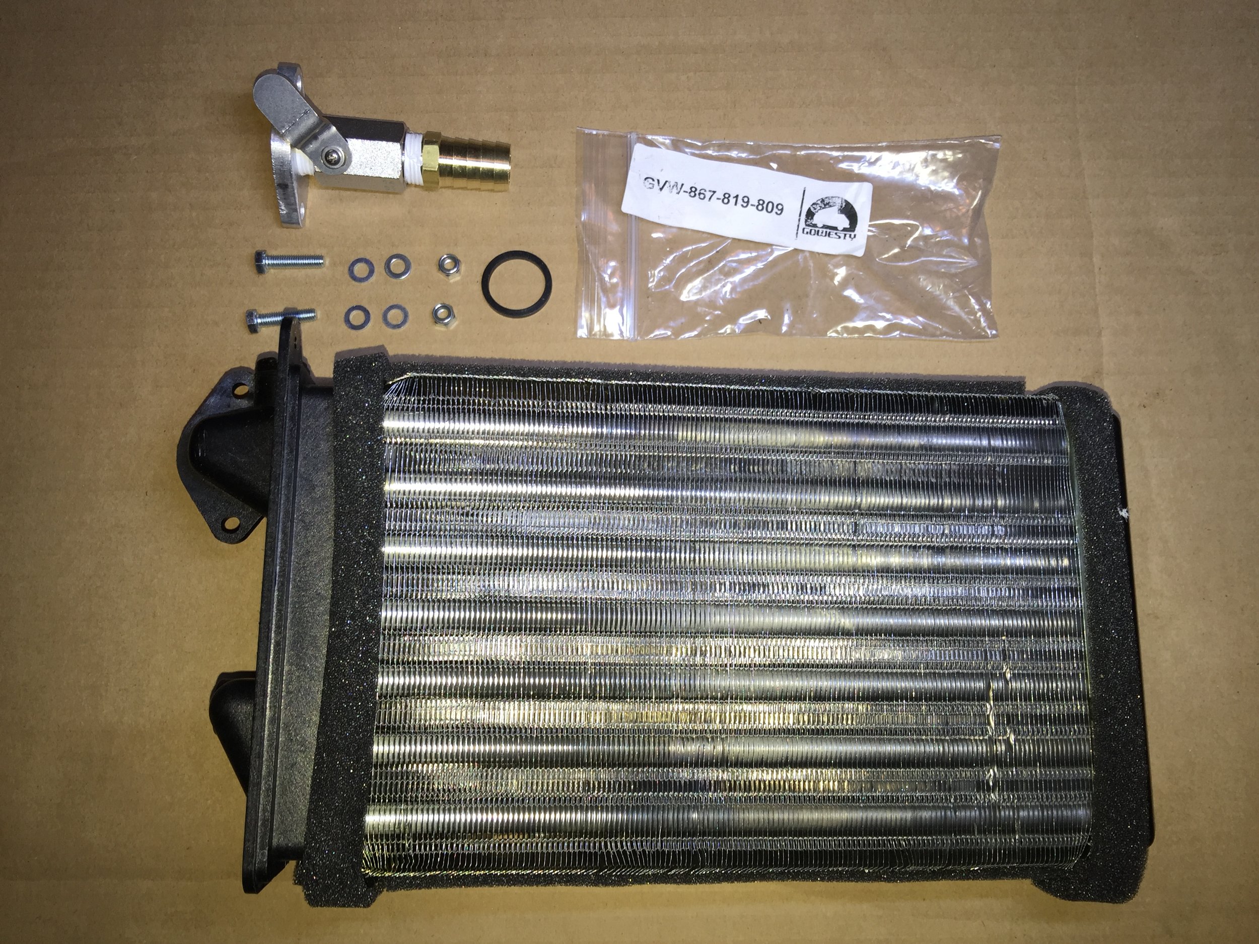

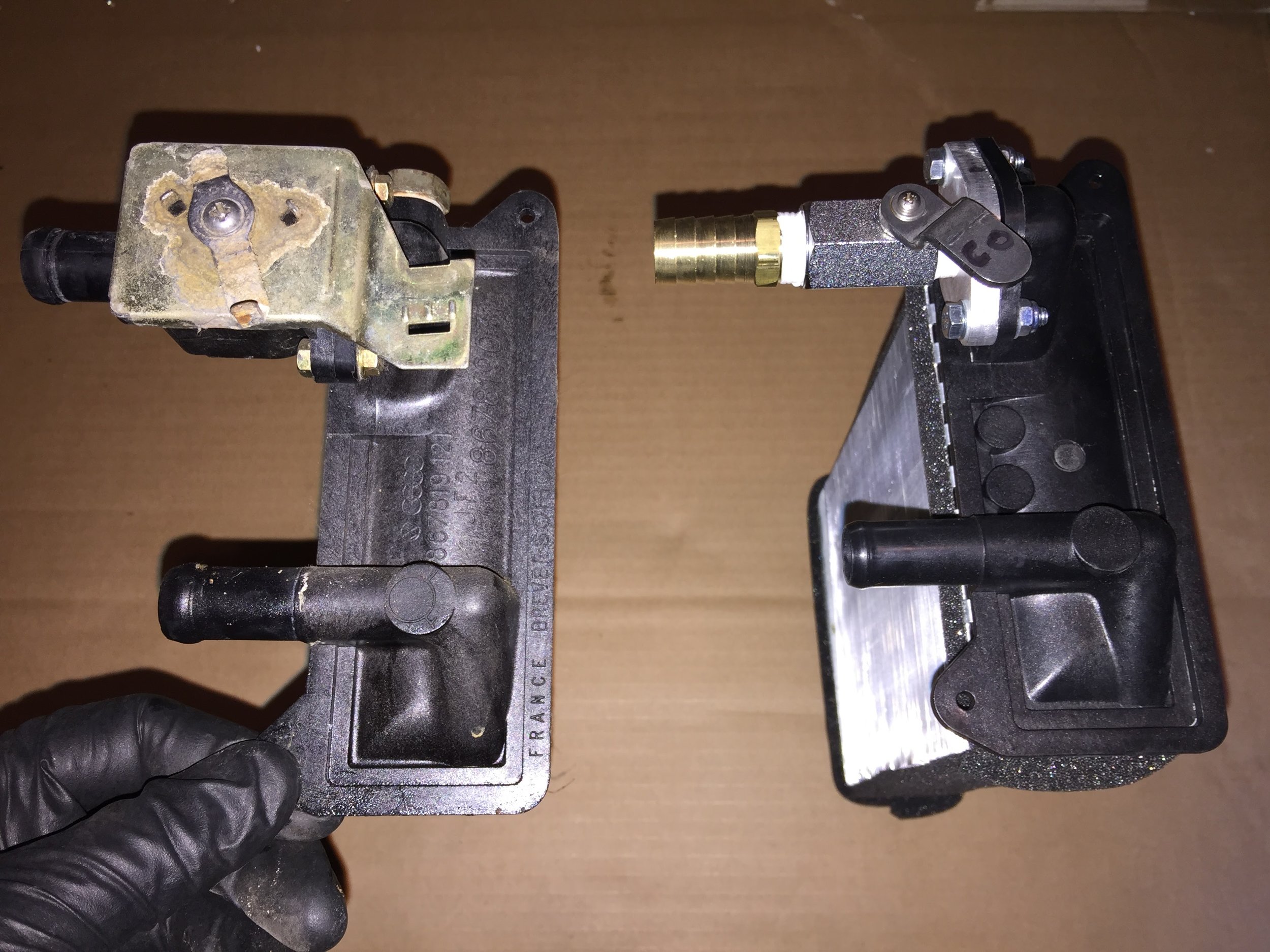
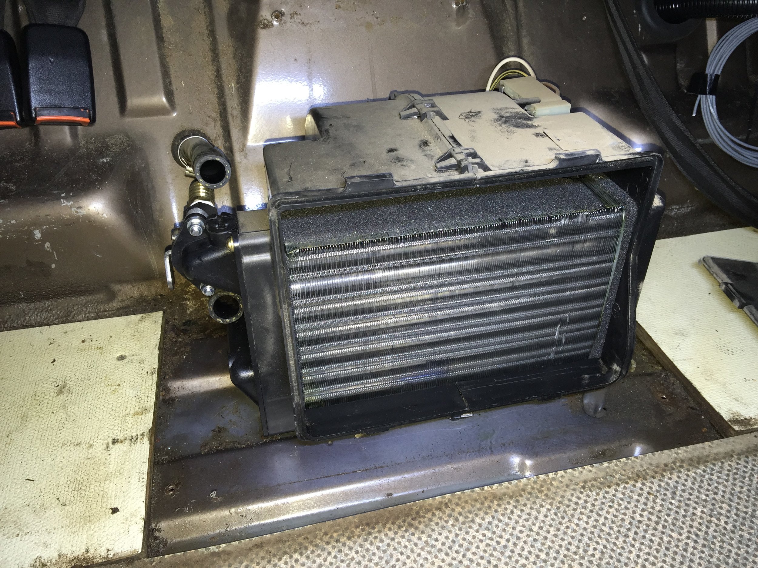
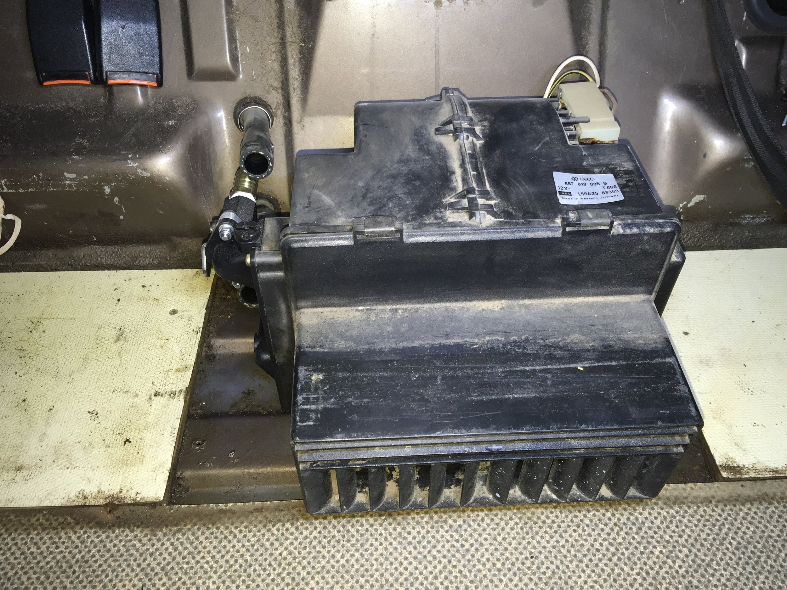
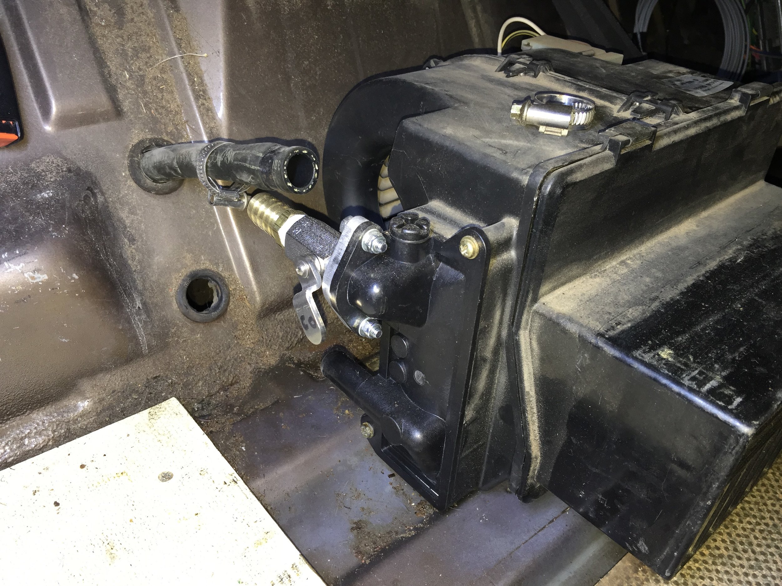
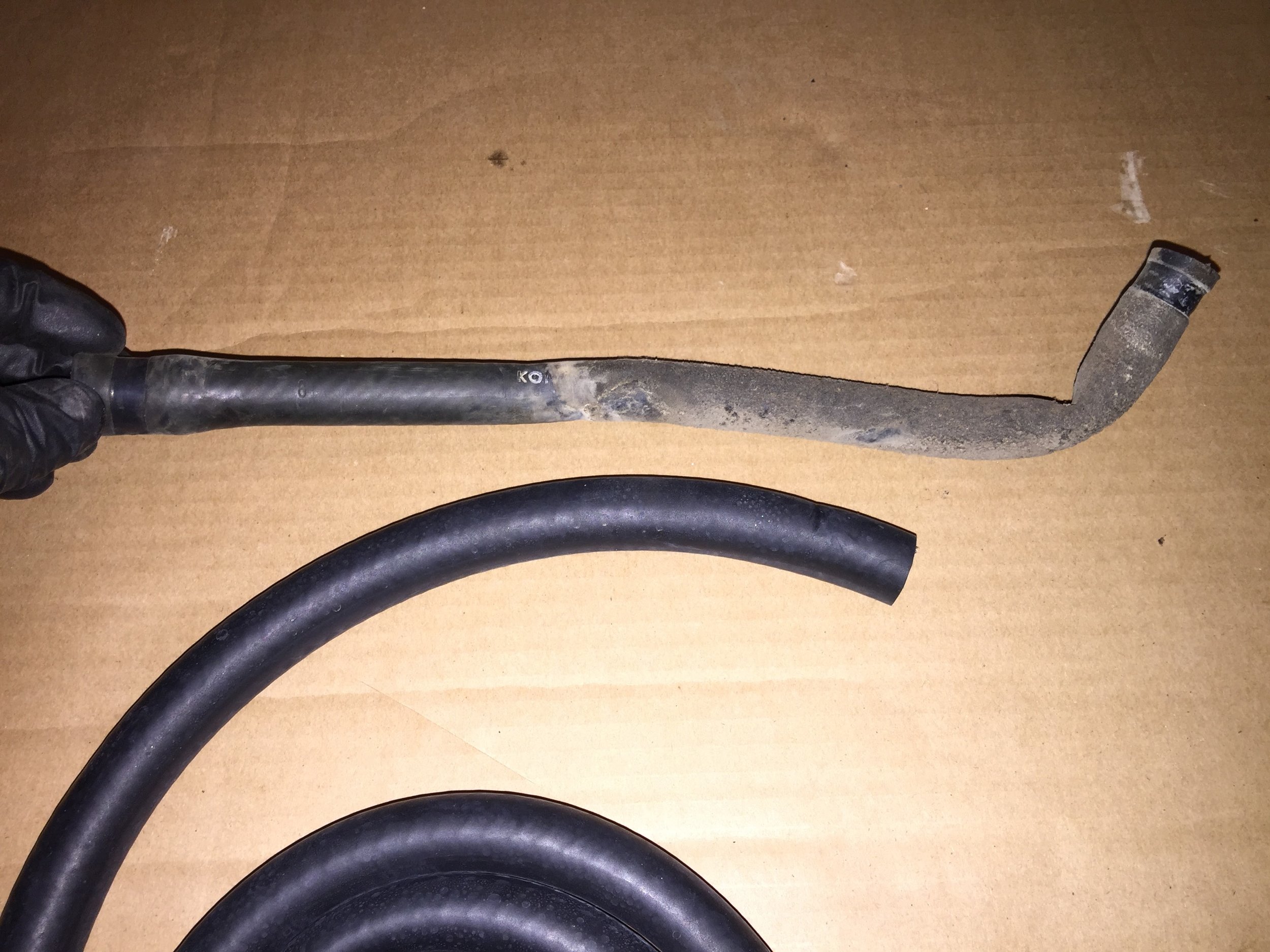
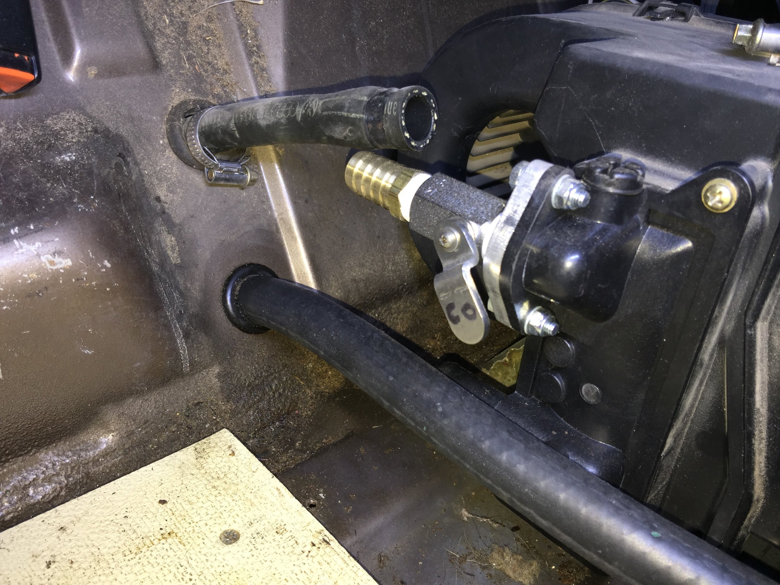
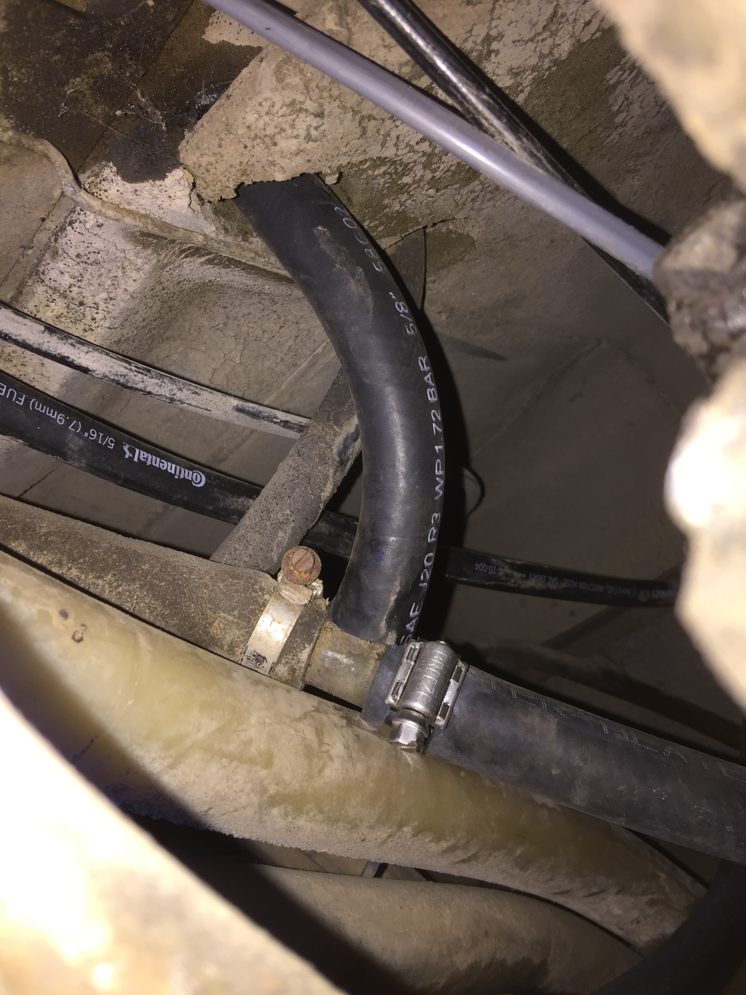
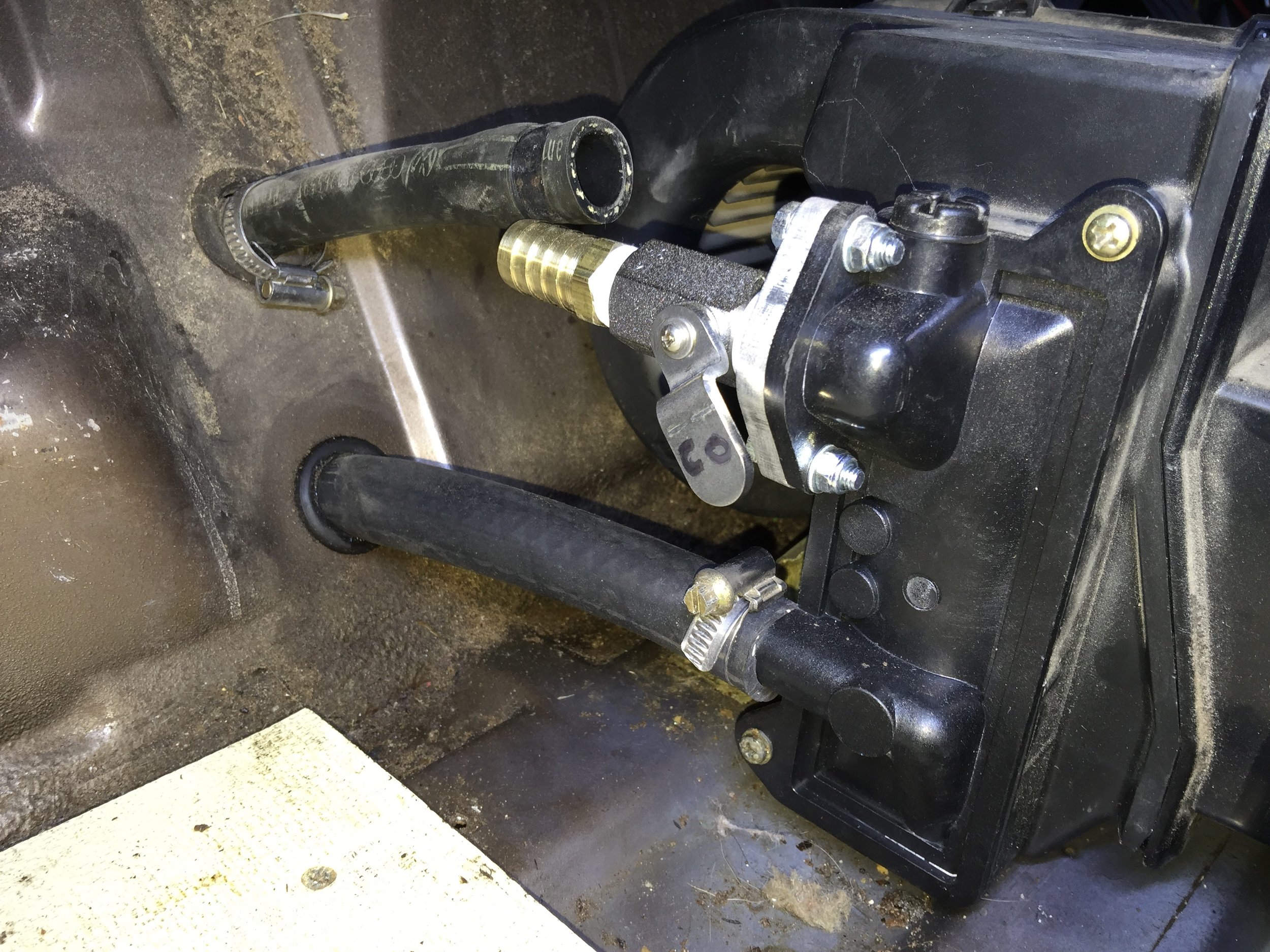
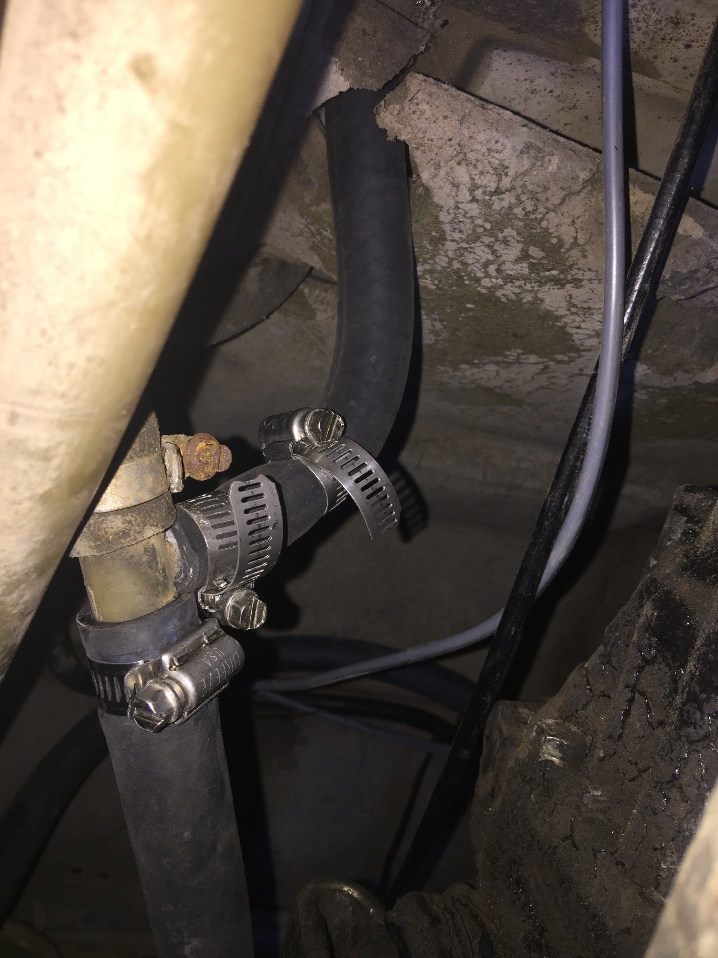
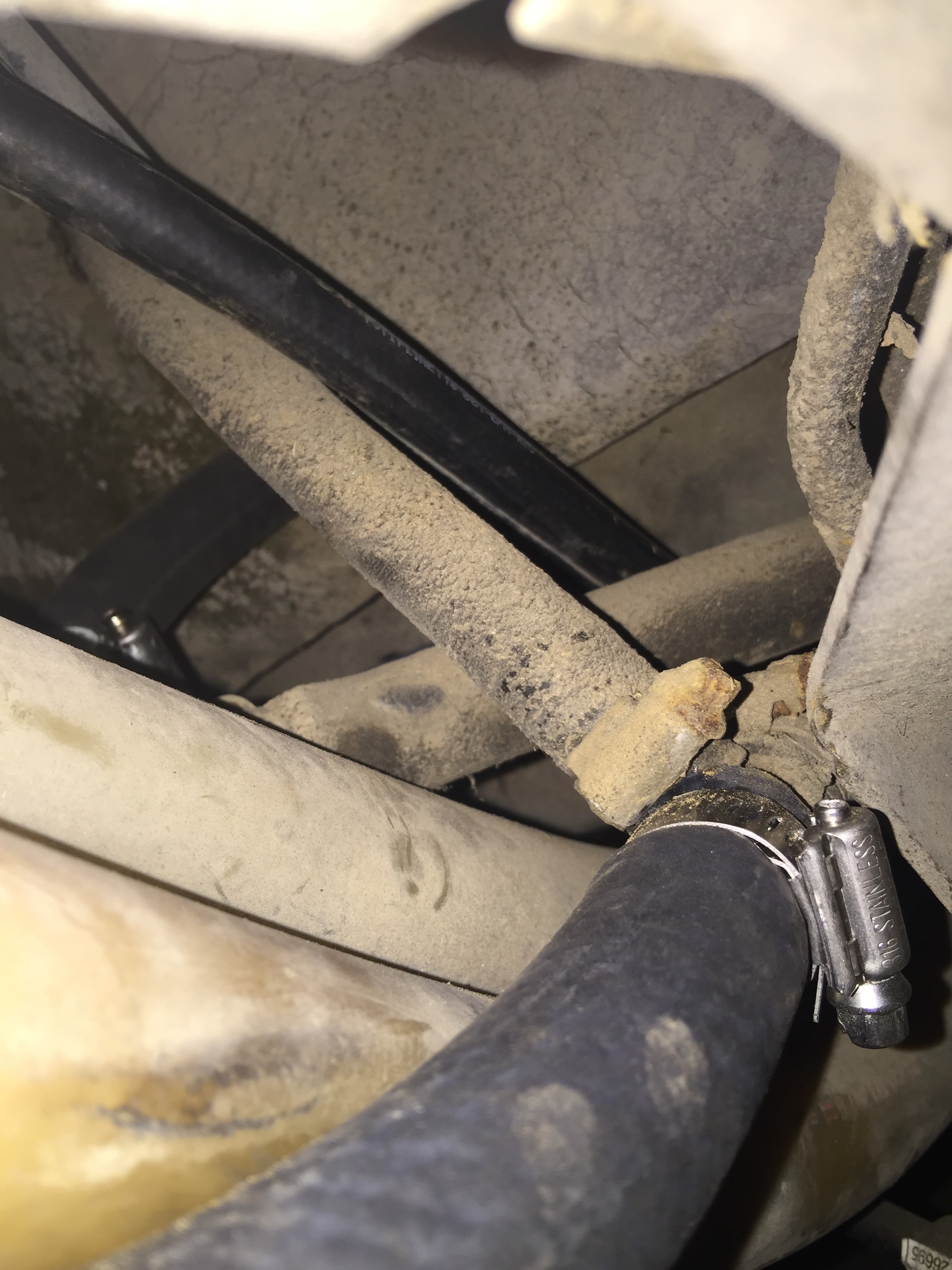
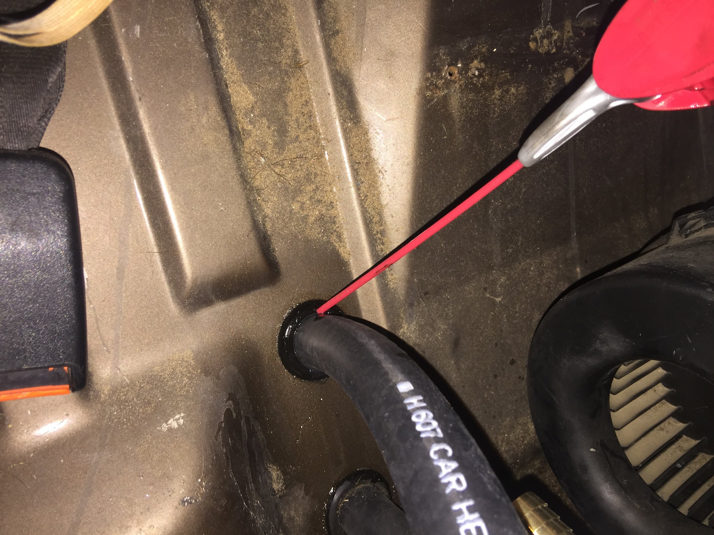
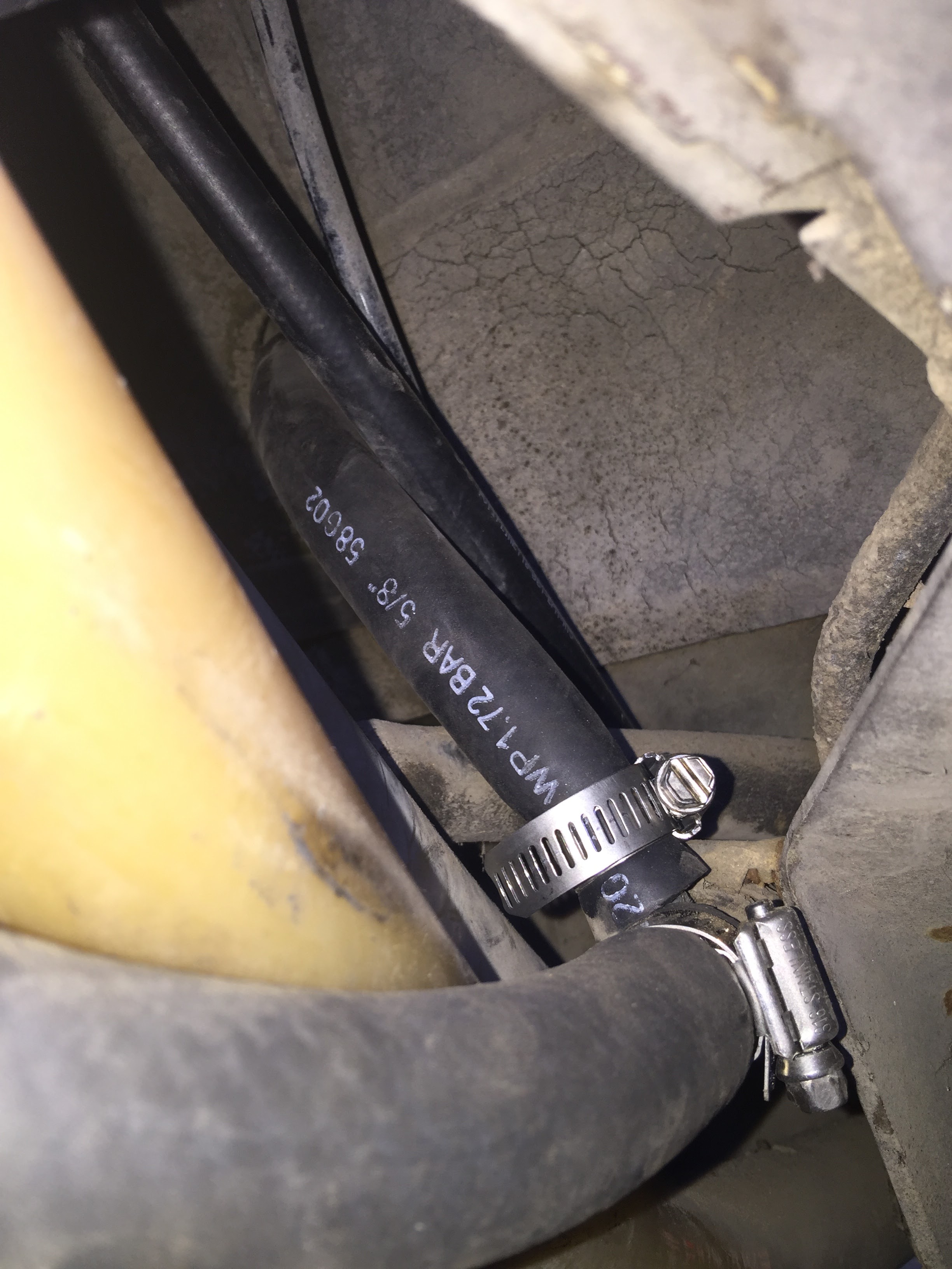
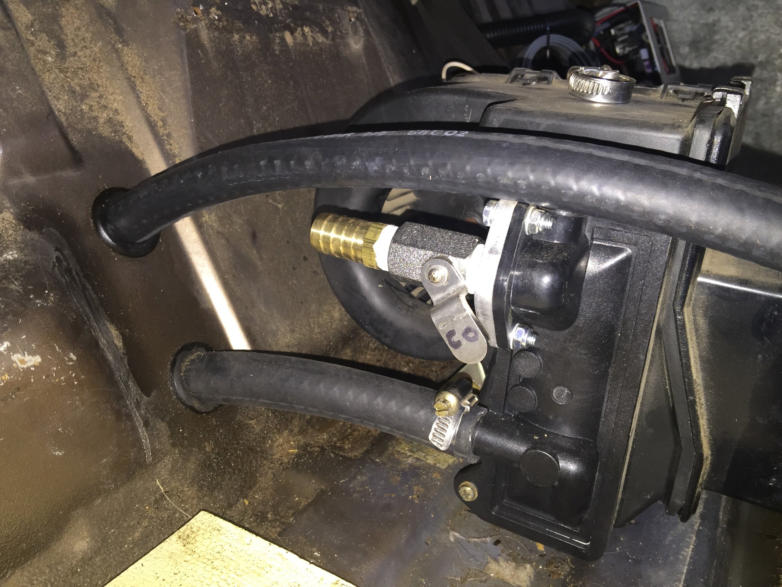
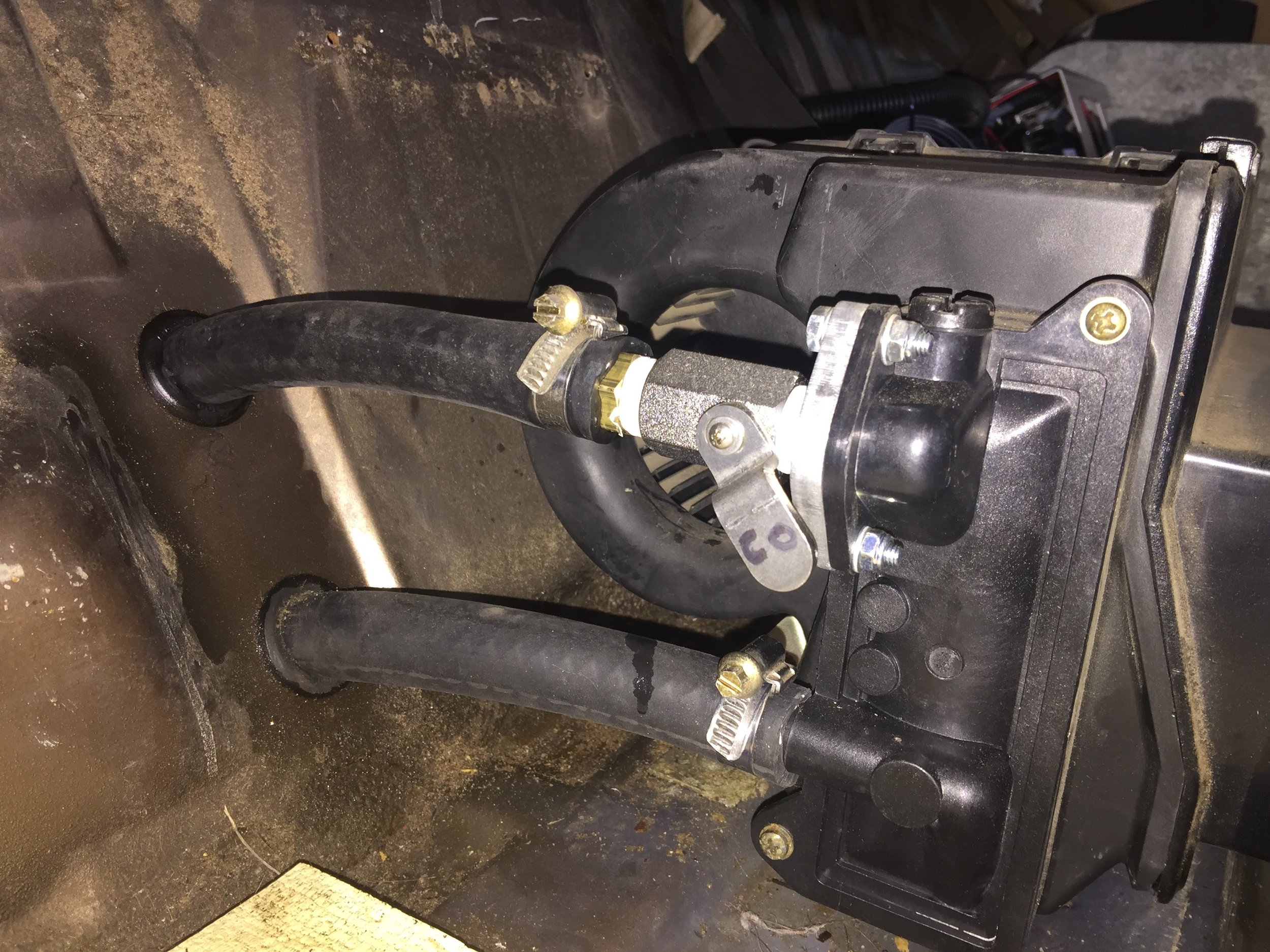
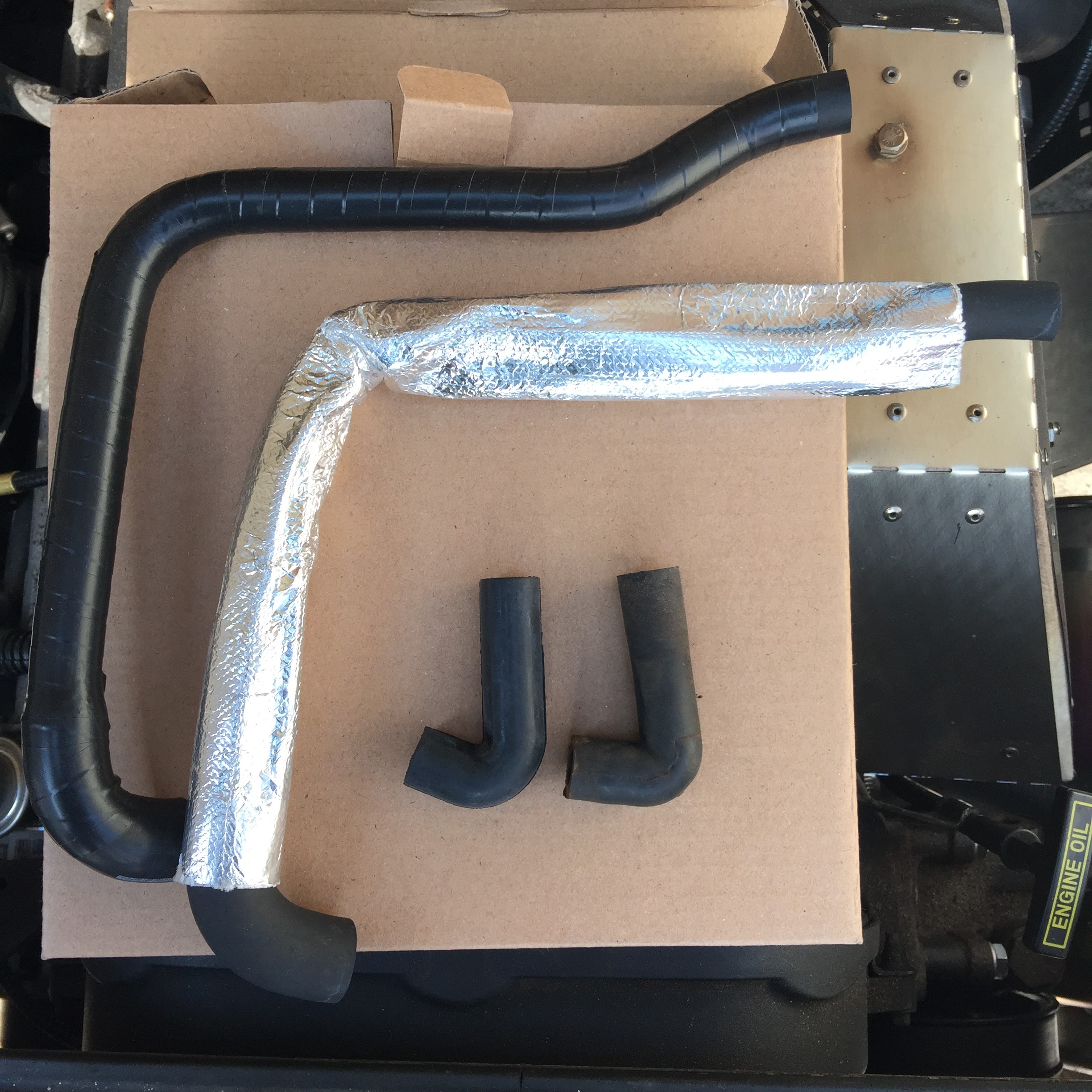
With the new core and valve ready to go, all that's left is replacing the two hoses. A little squirt of WD-40 at the grommets made pulling them through much easier.
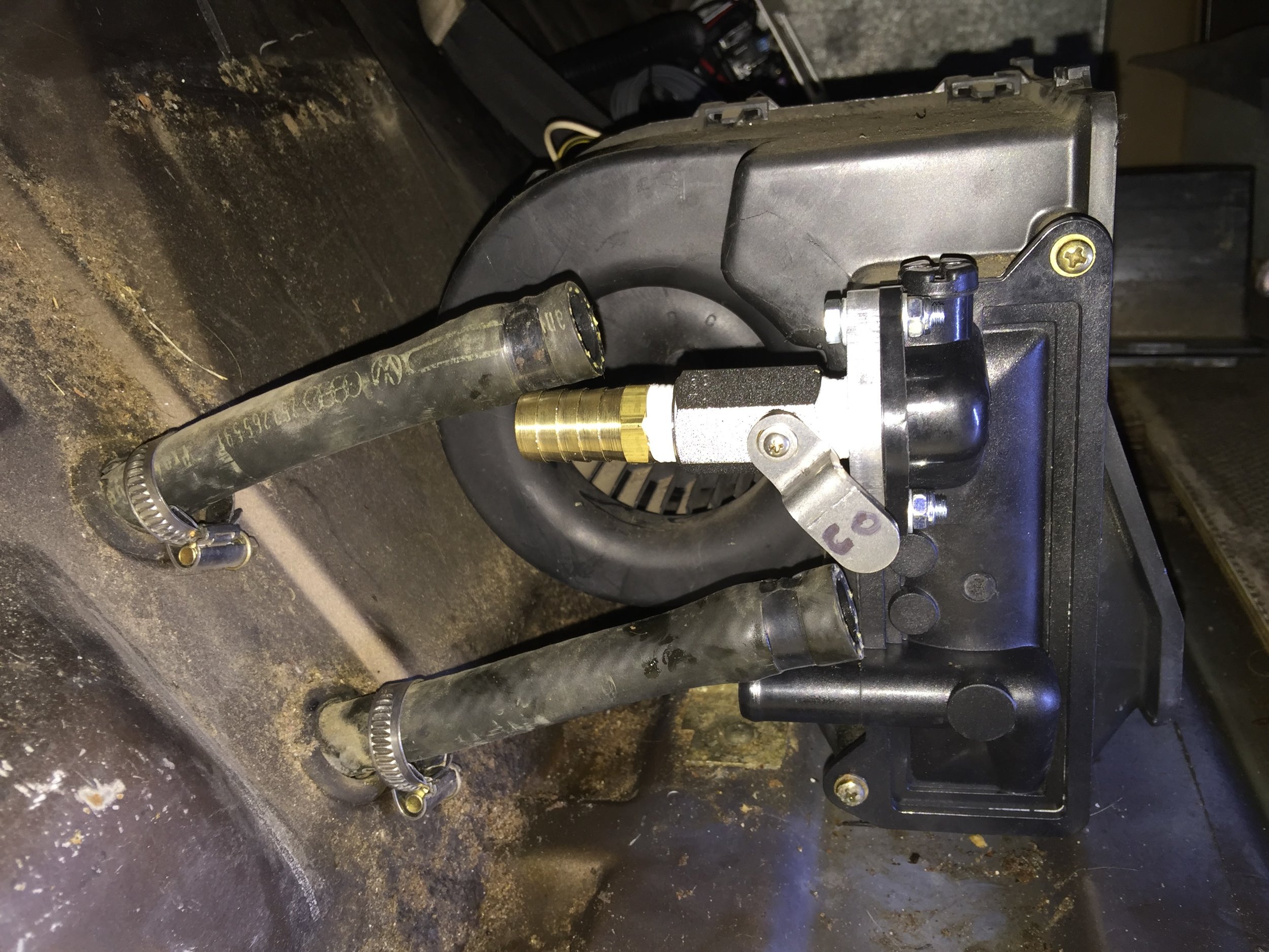
I didn't have the special little reducer that goes inside the supply line, so I just used another clamp and tightened the hose approximately half way. (8th picture below.)
I started with a 6-foot roll of hose and only used about 4-feet (last pic).
Finally, I labeled the new valve handle with "C" for "Closed", and "O" for "Open".

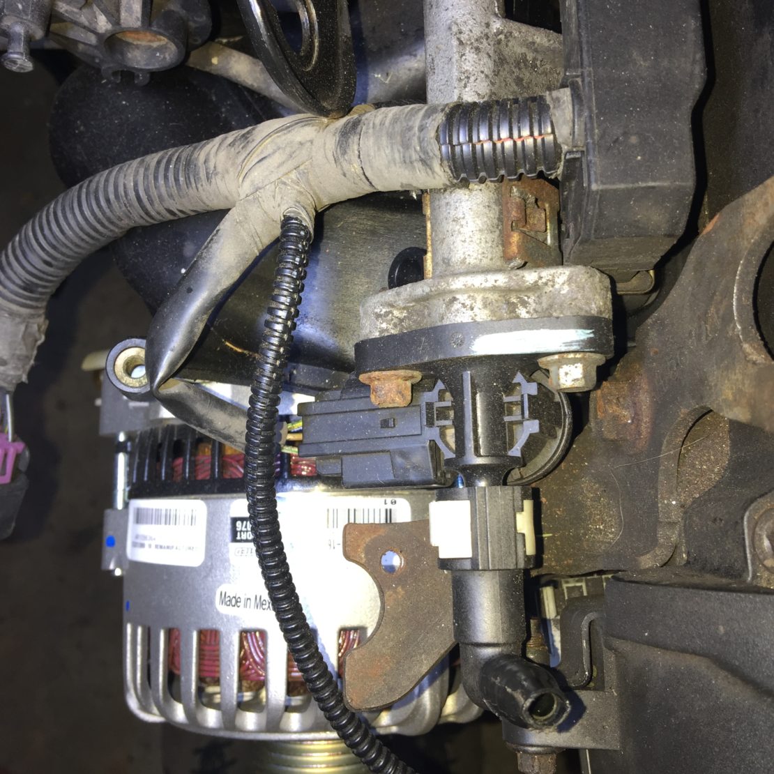
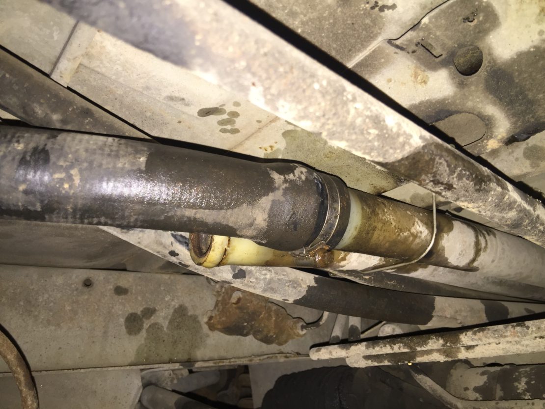
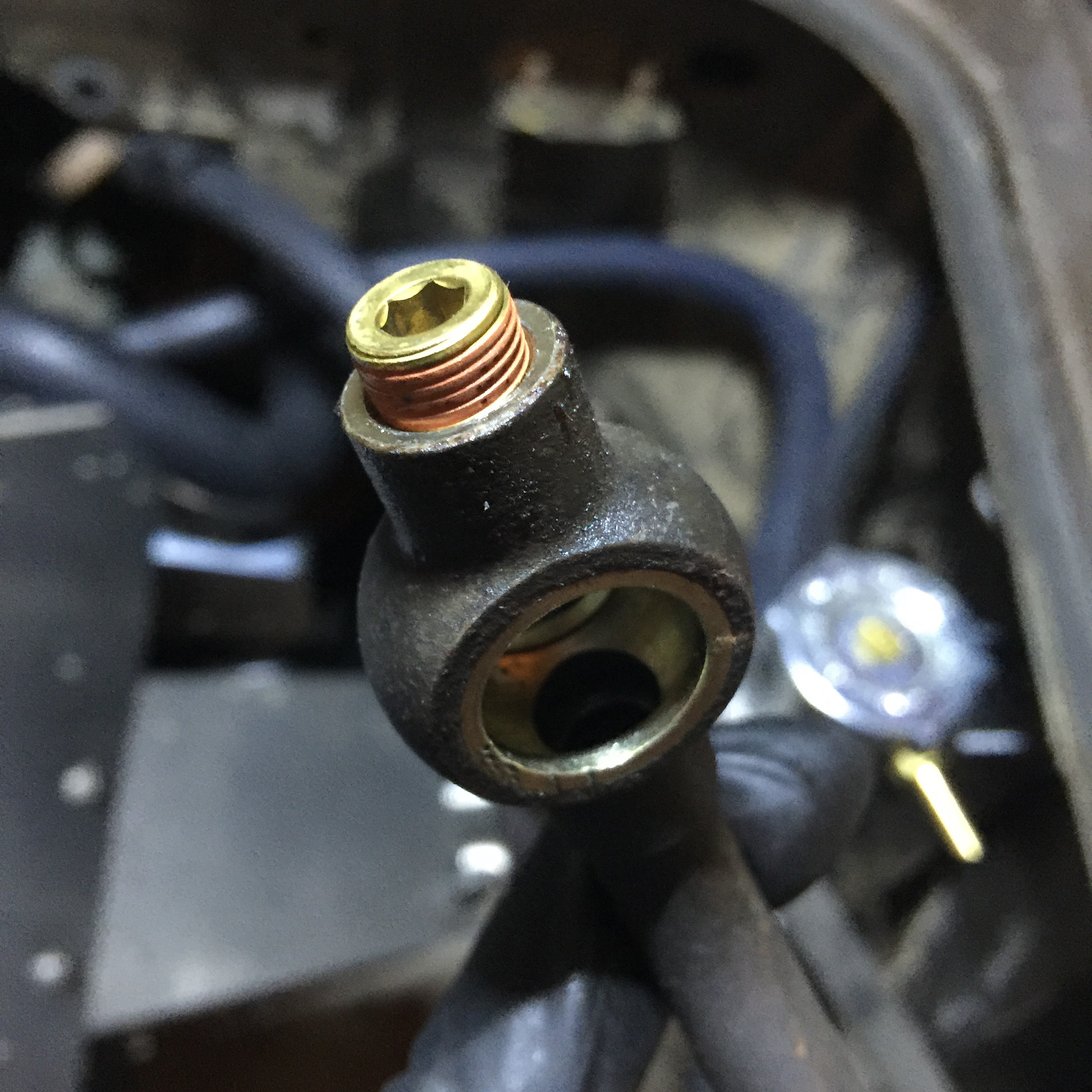
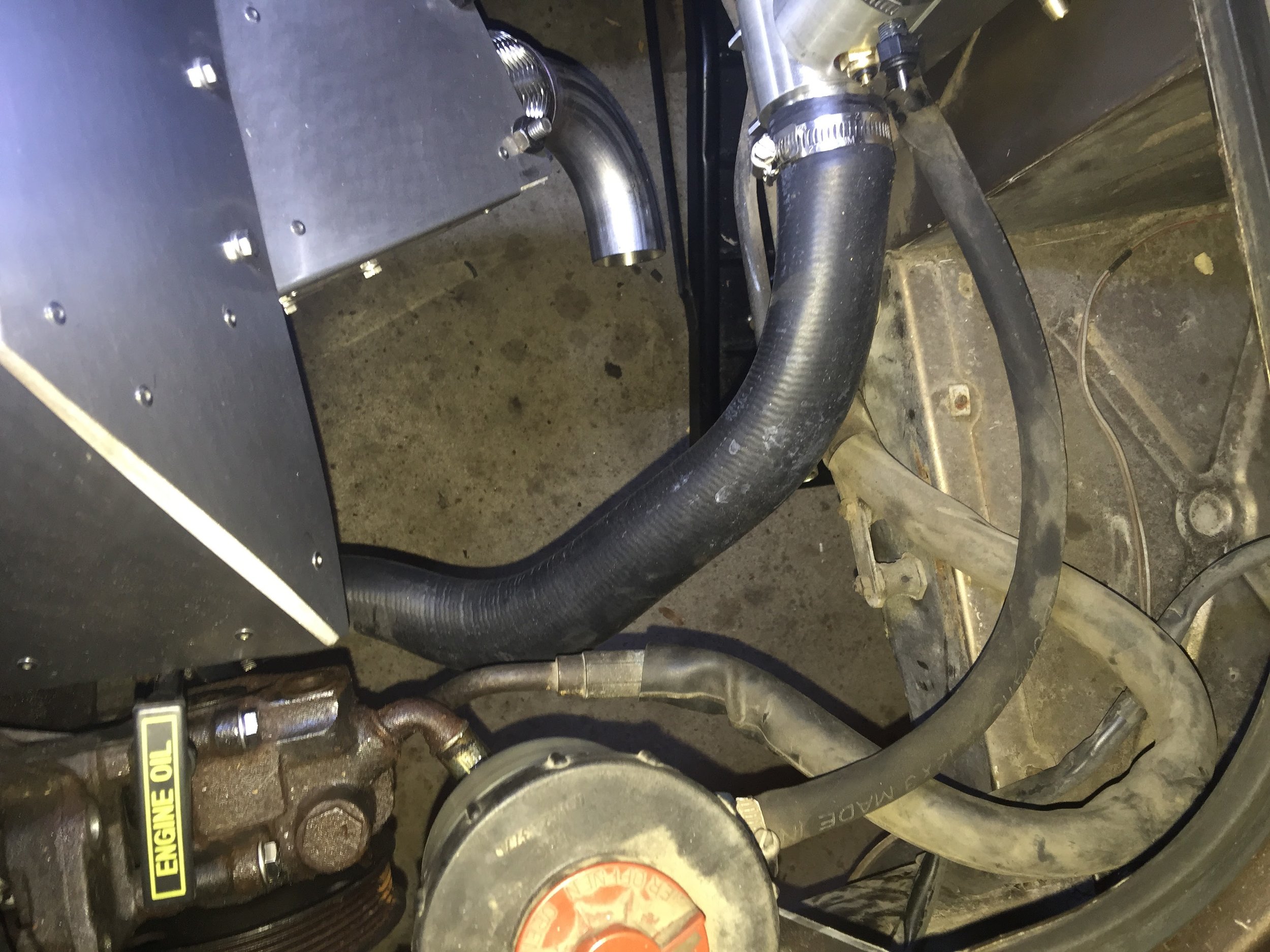
Power Steering
The instructions said you would need to cut the host to length. However, I seemed to have plenty of space so I ended up not cutting anything. Just made a bigger loop. I assume this is fine as long as it does not interfere with anything else.
Also, I didn't know what the "pressure sender" was and had to Google it. It's the two-pronged piece (third and fourth pics below) on the end of your power steering line. It simply twists off. You plug the hole using the hex nut/plug included in your kit.


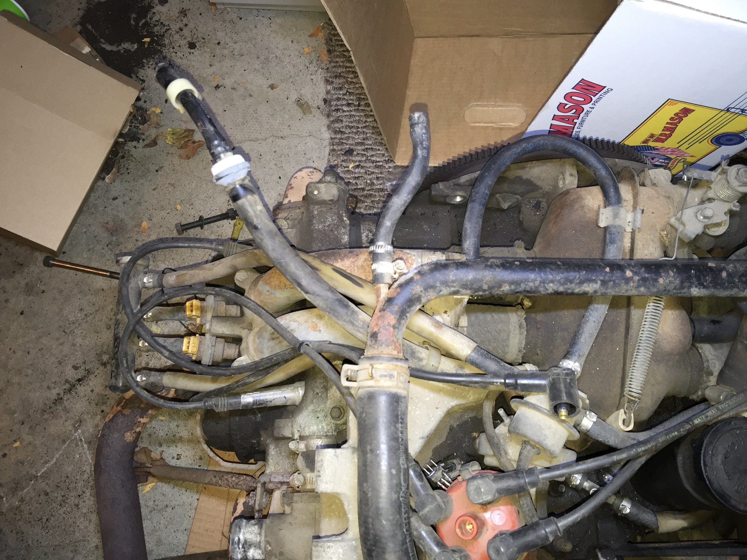
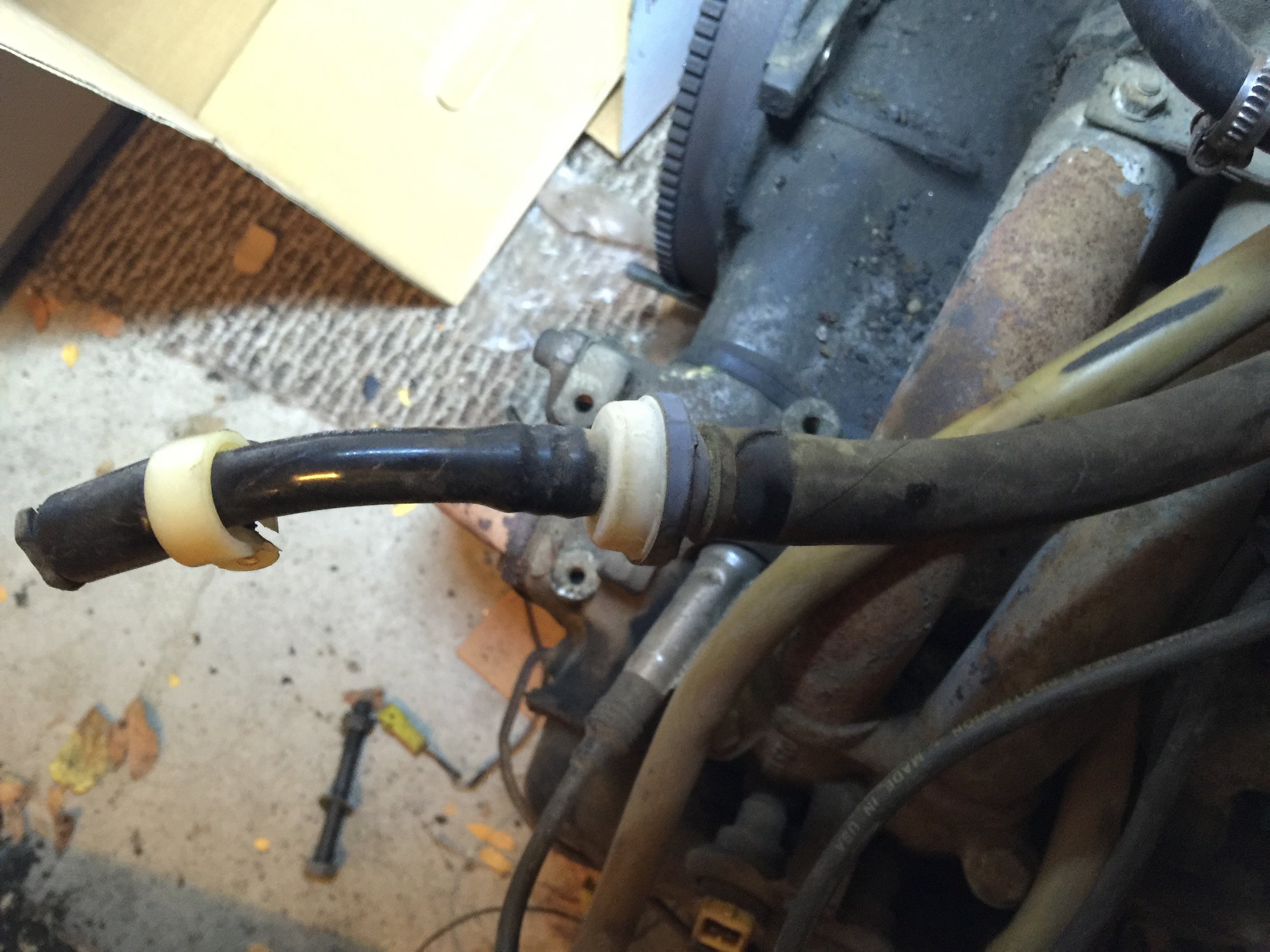
Brake Booster & Check-valve
The check-valve is reused from the old Waterboxer. I had no idea what this was, and it was glazed over in the manual. This is what you’re looking for:
Deck Lid Heat Shield
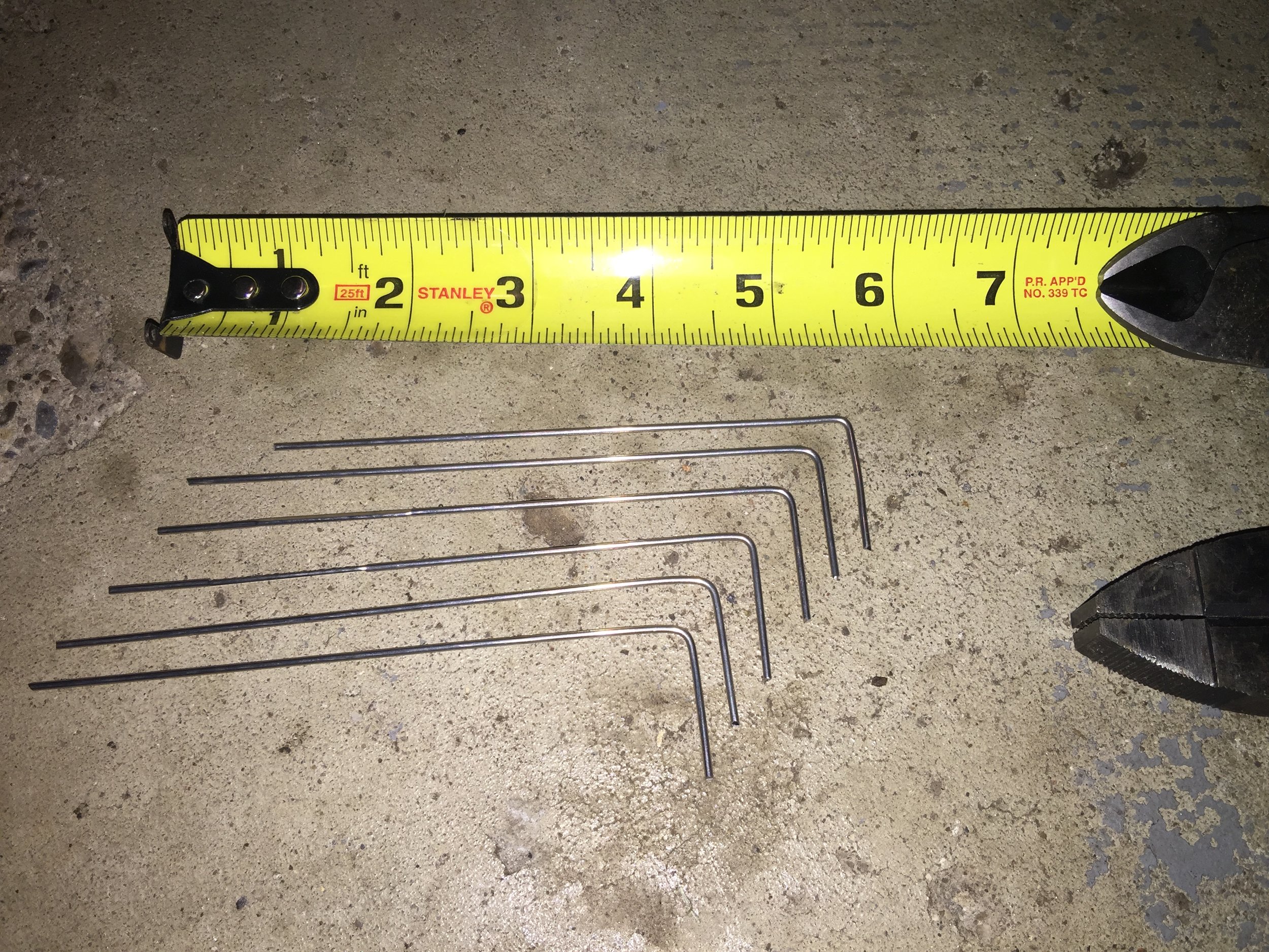
This is super easy. You're provided wire that you cut into 6-inch pieces. Bend them into an "L" shape. Insert into the existing deck lid foam. Then bend the wire to secure the new two-piece heat shield.
Once installed, double-check your clearance for the oil cap and the engine lift hooks. I was good on the oil cap (or so I thought) but needed to remove the lift hooks.


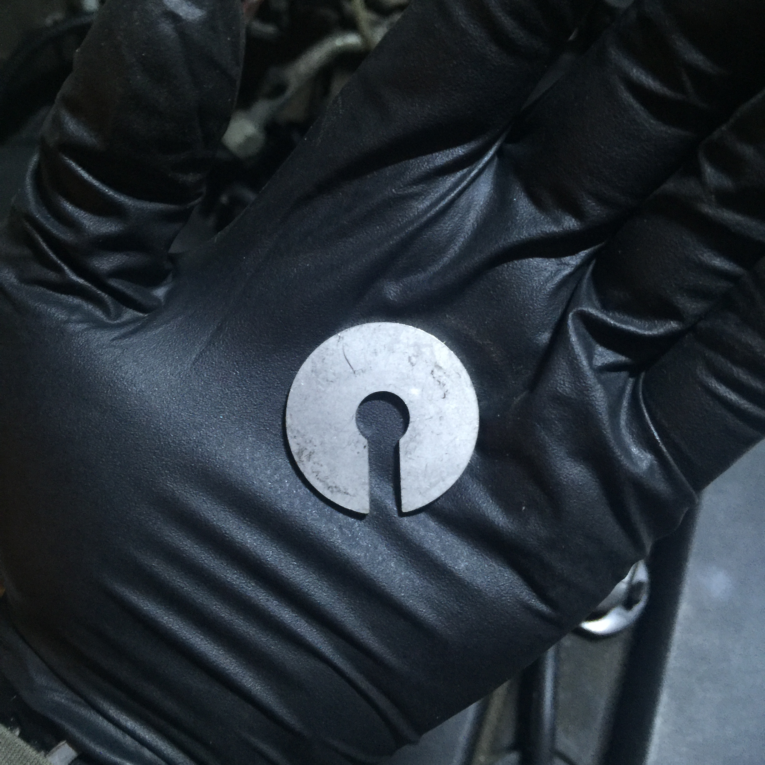
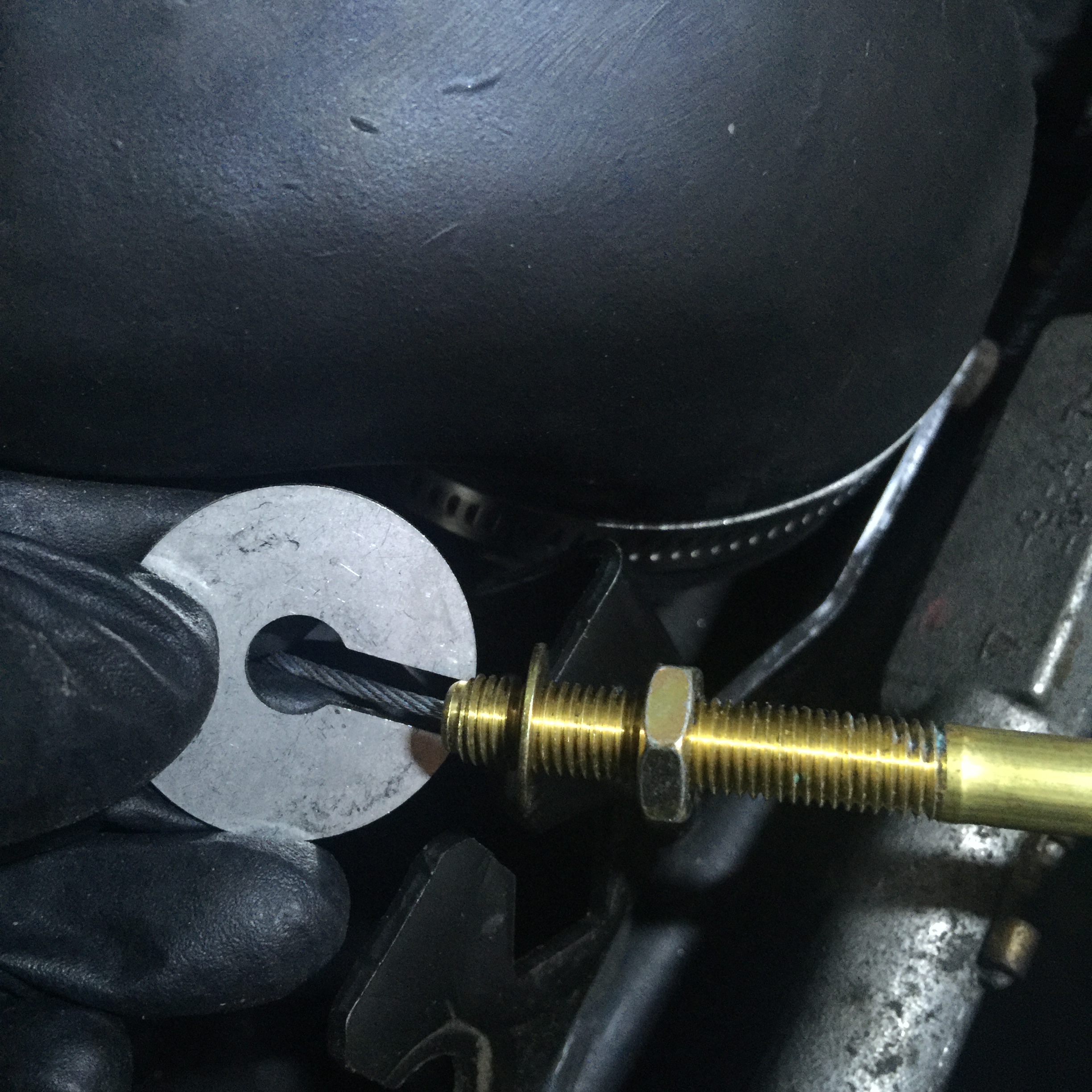
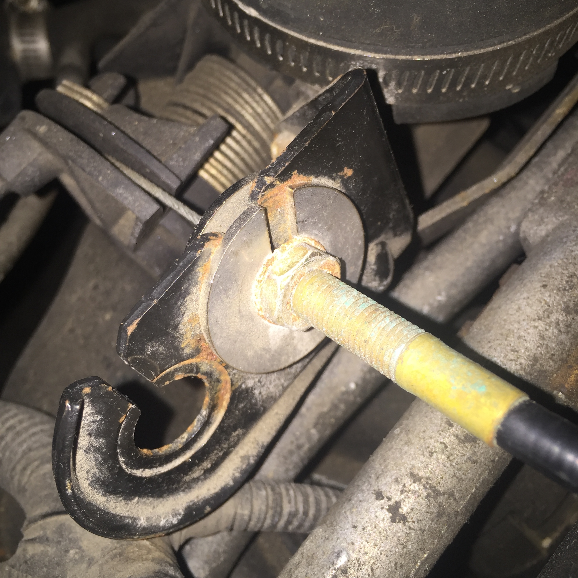
Throttle Cable
My main hangup was that the instructions said to not route the cable over the gas tank and to use the rear mounting tab. Not sure if there was a new cable in use, or if this varies by year, but I had to do the exact opposite to get mine to work properly. I routed over the gas tank and used the front mounting tab.
The only other tip I have here is you will need to push the gas peddle lever all the way up when you reattach the new cable. The first time I attached it when it was all the way down. In hindsight, duh, that didn't work. Luckily it's pretty obvious if it's hooked up wrong, and pretty easy to adjust too.


Bostig Exhaust Heat Shield
This is Bostig's upgraded heat shield. If you're interested, unfortunately you're out of luck. Just a couple of months after my purchase it was permanently sold out, so apparently I scooped up one of the last few. However, I recently saw on Bostig's Facebook page that they are working on a new version. So, if this is something you want, cross your fingers and keep your eyes peeled. Otherwise you're out of luck for now.
Admittedly, it was a relatively pricy upgrade and definitely not required. I opted for it due to better heat protection (obviously), and that it's a permanent solution. It also looks nicer, so I suppose that's worth something. I believe the stock Zetec heat shield calls for replacement every 50,000 miles. One less thing to worry about by going with the Bostig version. In addition, I ordered it out of convenience. Took me five minutes online and it showed up at my door a few days later. Tracking down the stock heat sheild from a junkyard would have easily taken me a couple of hours at least.


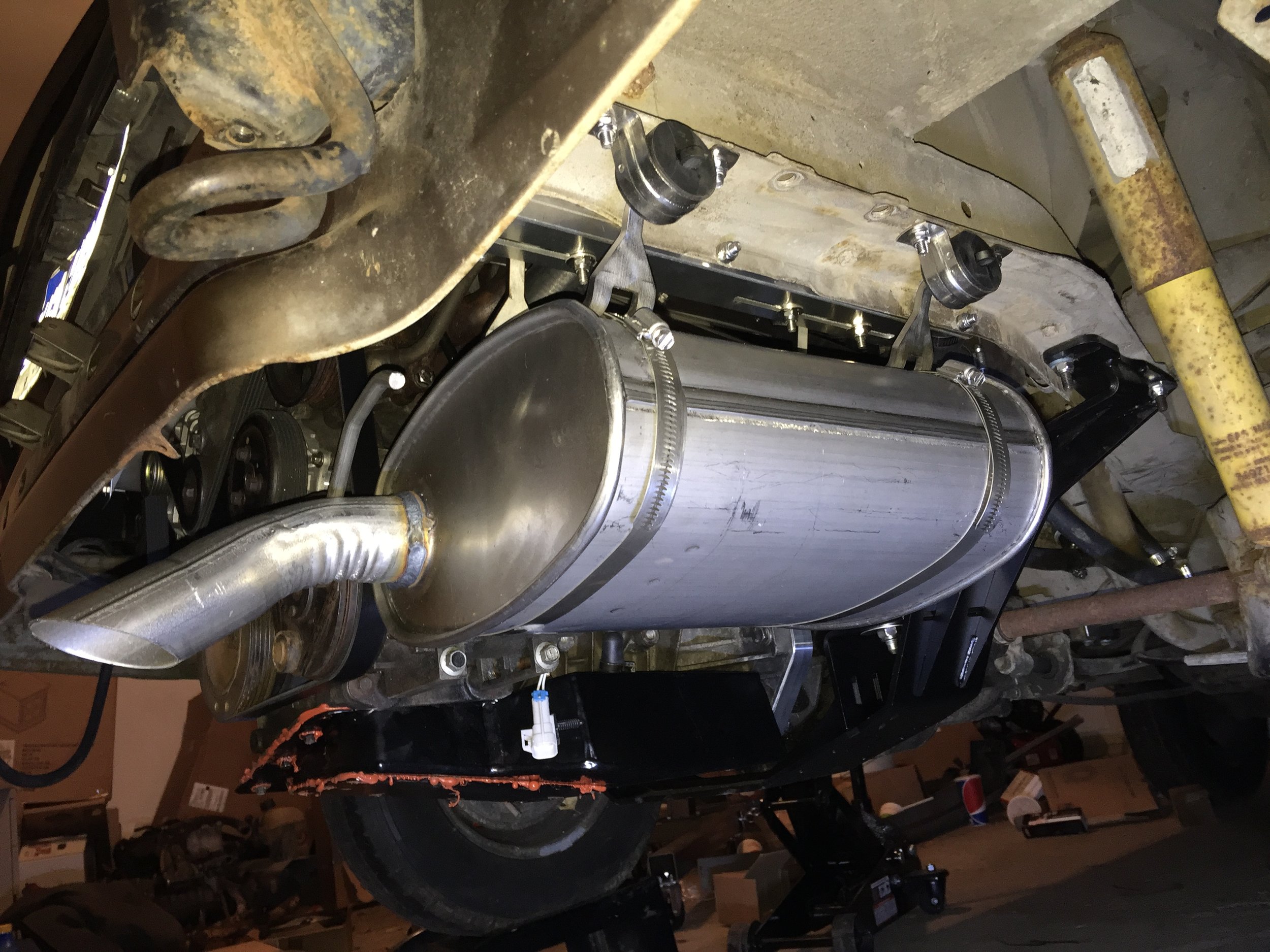
Exhaust
This is another thing that's "way out of order" compared to the manual, but I saved the exhaust install essentially until the very end. I can't take credit for this idea, but I will surely pass the tip along. You'll be glad you saved this until the very end, as the exhaust is one of the bulkier items. The extra elbow room is nice to have, to say the least.


MIL (Malfunction Indicator Light)
I never hooked my MIL due to using an UltraGuage. I'll probably hook it up some day simply for the sake of thoroughness, but considering the UltraGuage does many times more than what a simple dummy light does, this is very low on my priority list.
UltraGauge
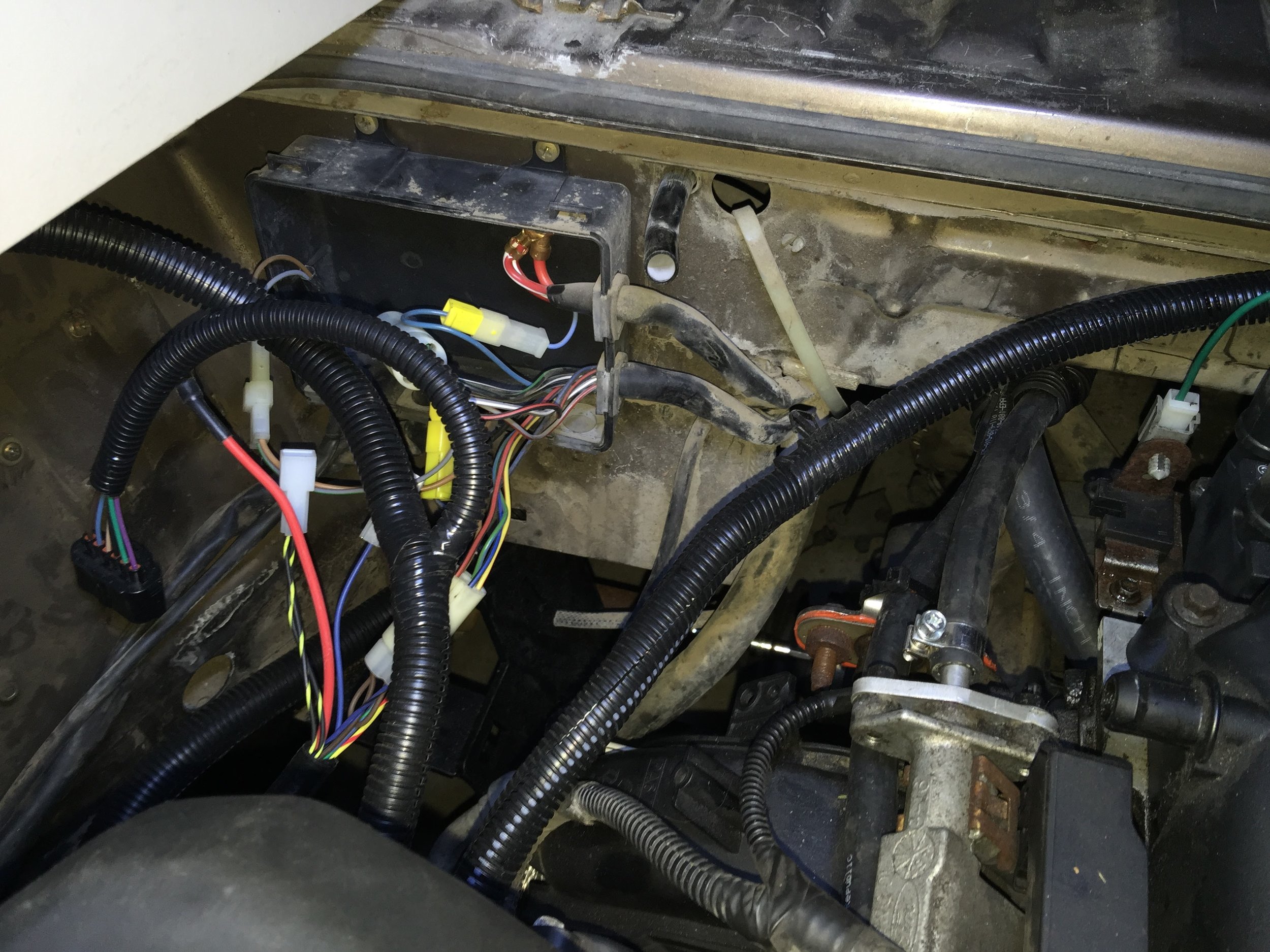
Final SK-W Connections
The end of the install is near! With all of the mechanicals permanently installed, it's time to button up the final SK-W (Wiring) connections. Everything is securely in place using lots of zip ties. I probably looked everything over four or five times making sure I didn't forget something.


PCV Valve
At this point you're so close to being done you can practically taste it. However, you'll likely look around and see some random parts hanging out. I did pretty well, all I had left was the PCV valve. Super easy, as no tools are required. Simply pull the old one off and install the new one.


Fill Fluids
This is pretty self explanatory, so didn't really take pics. Just don't be a dummy and forget! Oil, coolant, and power steering fluid for this van. The coolant was the hardest / most annoying part. Lots of squeezing of coolant hoses to help purge air from the system. As you can see in the pics, I used this fancy Lisle funnel. I was a little skeptical when I ordered it, but it actually worked very well. It was nice to have a large reservoir to work with. I could easily squeeze out big air bubbles and not worry about overflowing and making a mess, not to mention wasting a bunch of new coolant.


Load The Tune
You will need a Windows computer to install your custom tune from Bostig.
Depending on your computer background, this will either be a piece of cake or a major headache, ha. I have a pretty extensive background so this was no big deal for me. If you have a problem call SCT right away. You simply download the software from their website and install it. This should be a quick process, mine was not. I messed with it for about an hour thinking I was the problem. Turned out, something was getting mixed up on their side. My total support call was less than 10 minutes before they had me up and running. Suffice to say, SCT support was excellent! I should have called them after 10 minutes of trying, not an hour.
Again, assuming you know how to download and install a program from the internet, this should be a quick process. If you run into any hiccups call SCT right away. They were super helpful and can remotely take control of your computer and fix things for you. Don't waste an hour trying to fix things on your own like I did!
Once I had their software installed, loading the file onto the SCT handheld device was painless. From there, you hook up the SCT to your newly installed ECU, transfer the file to the ECU, and you're done. Apparently I didn't document much of this with pics, which I guess makes sense. Here's a couple of me loading the tune from the SCT to the ECU.


First Start
The moment you've been waiting for is finally here! Well, almost. First, four new spark plugs.
I actually tried to start once before this, but it was totally dead. After a quick review I realized I had hooked up the starter wires improperly. Doh! Luckily I had taken a picture before I disconnected it a couple of months prior. Using that picture made it an easy fix. A few minutes later and I was ready to try again. I also started a data log.
TIP: When data logging...every time you key-off the ignition the recording will fail and it has to be restarted! It took me several partial / failed logs to finally realize what was going on.
The video is admittedly pretty lackluster from this point of view, but it's exciting in the moment!
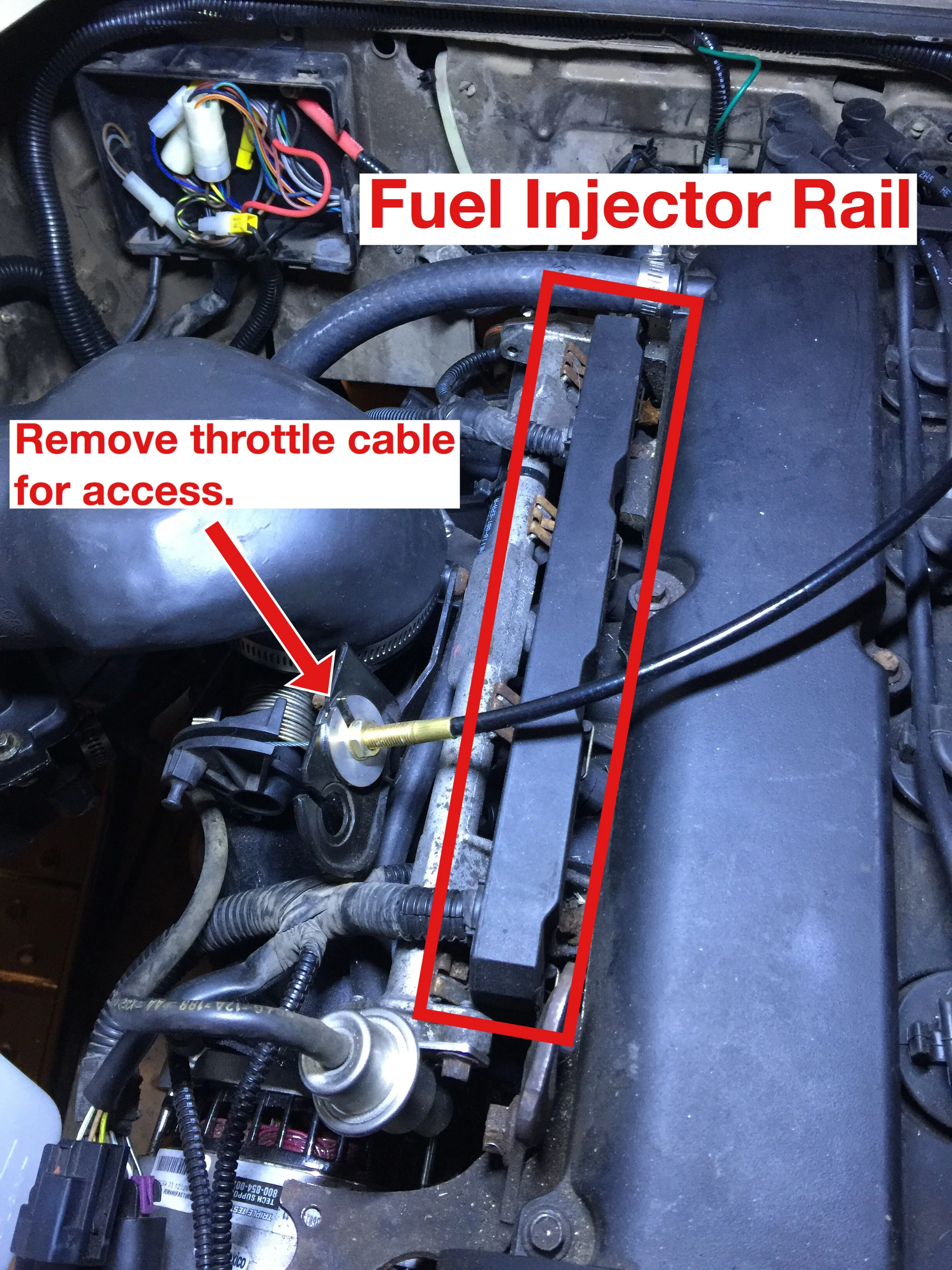
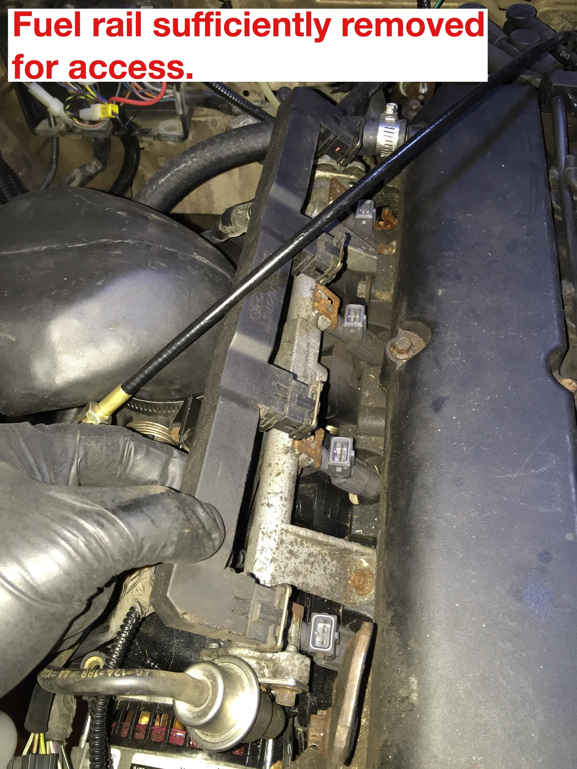
Coincidentally, I shut it down just as it seemed like it was ready to stall on it's own. I sent the video and data log to Bostig for review. Things were off due to misfiring, so I did the "injector shock" procedure / test. To gain access to the injectors, you need to first remove the fuel injector rail.

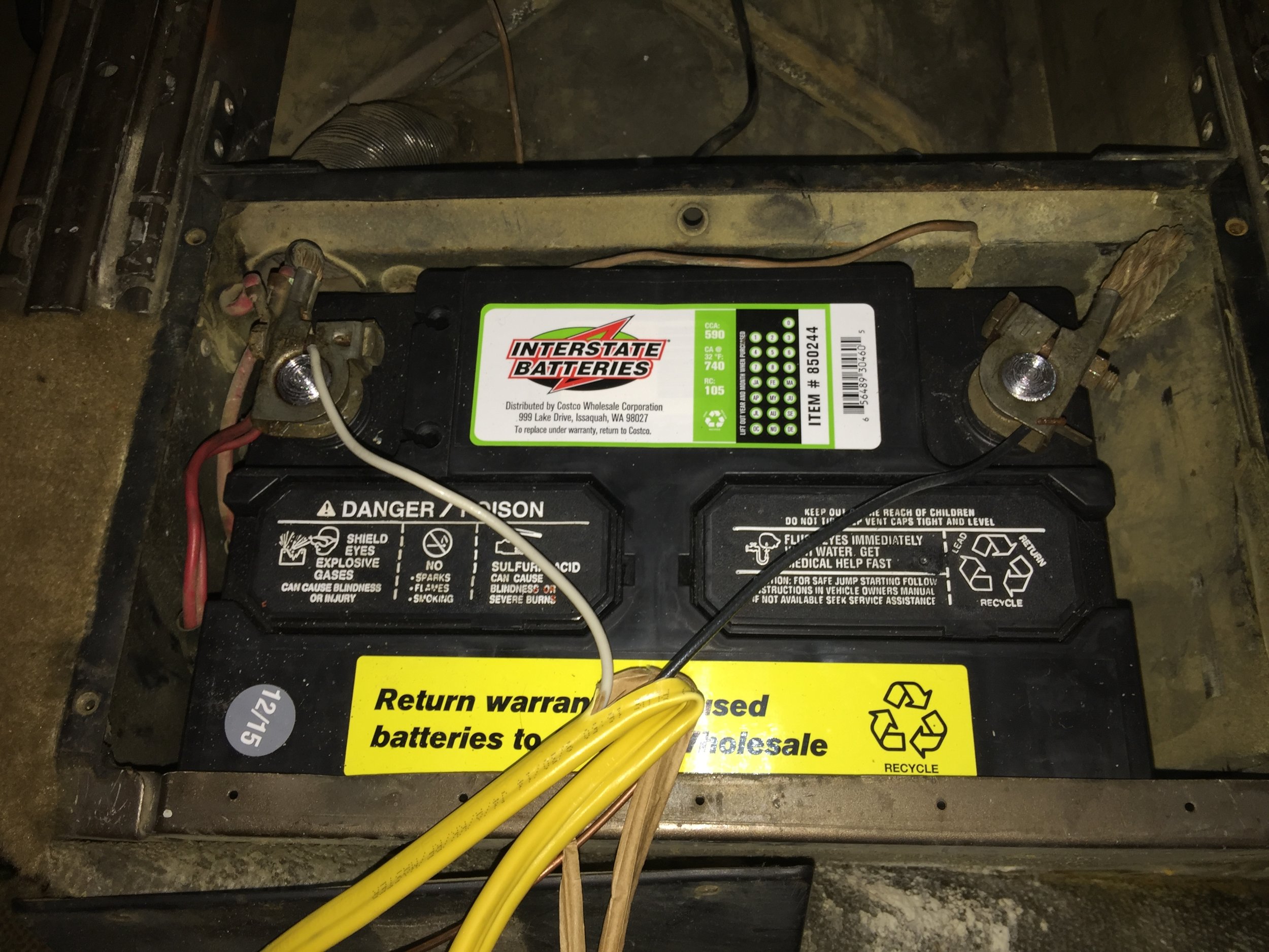
After that, I simply connected a spare piece of 12-2 Romex wire I had laying around to the van's battery. On the other end, I held one wire in contact to one of the spades on the injector. (Polarity does not matter.) Then using the second wire, I started tapping away. Make sure you DO NOT short / touch the two wires together!
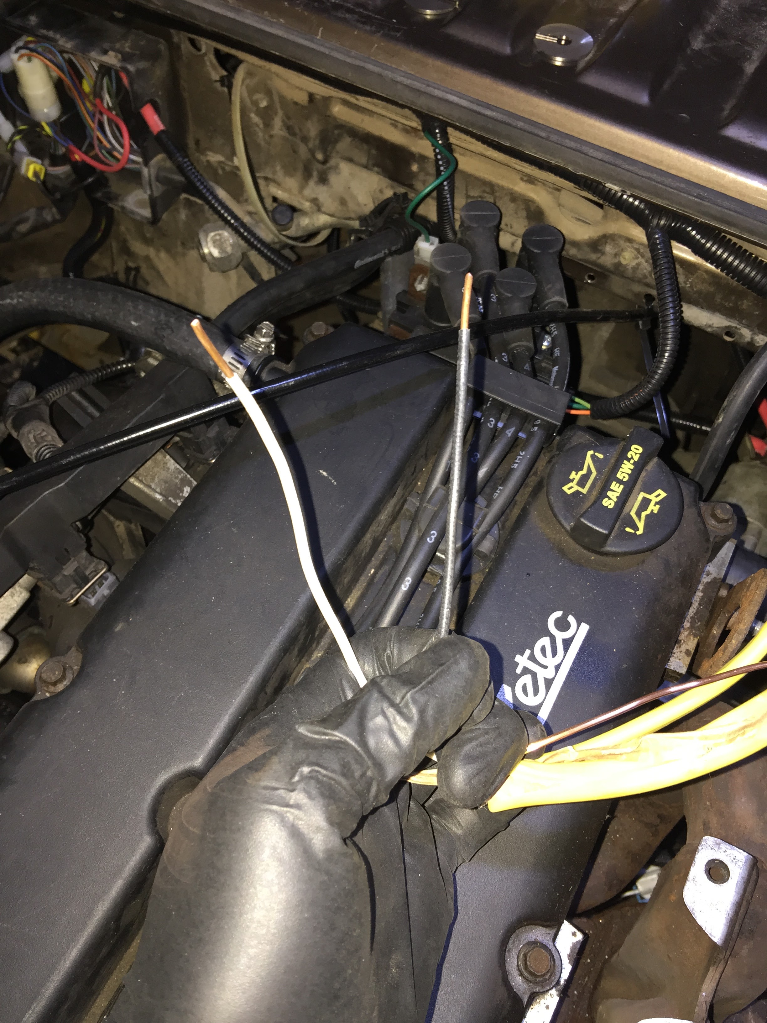

I did this shock test many, many times actually. Literally thousands of shocks later I could still never hear the "click", or if I did it was much more quiet than I was expecting. Apparently I'm deaf and/or dumb. Not sure how to get that diagnosed!
Some revving RPMs made it into the mix, too. That was tracked down to a poorly performing IAC. After several cleanings and no luck, I replaced it with an off-the-shelf one from a FLAPS.
Don't do this! We eventually learned that it worked only good enough as a stop-gap. A month later I did a warranty return on it and picked up a genuine Ford / Motorcraft one that was double the price. $60 vs. $120. The difference in performance was immediate and significant.
As you might imagine, this all took several days to sort out. Part of the problem was that I was working in a borrowed garage that's a 30-minute round trip from home. So, it came to a point where I had to coordinate schedules with Bostig so I wasn't completely wasting my time. At this point the manual didn't really help much, as trouble-shooting for each installation will be different. This is where Bostig's support was priceless!
Ironically, that silly shock test is where I got hung up the most. Who knows what the heck was going on. It seemed so simple but yet it still didn't seem to work right for me. This shock procedure apparently worked (finally!), or there's a possibility that by simply starting and running the motor several times it helped clear out old residue. Who knows. Either way, once that worked itself out, and I swapped in a new IAC, the engine was running markedly better.
One final note here...there is MUCH more smoke than I was expecting for the first few starts. This is mostly caused by manufacturing residue being burned off from the new exhaust parts. So no big deal. It goes away eventually, but just be ready for it. I definitely had an "oh crap" moment when I first saw all of the smoke. Since I sent a video, I was reassured that it was all coming from the exhaust. It took a good two or three starts, some of which had 10+ minutes of idling, for it to fully burn off. (I had some longer idle times due it being winter and needing to get the engine up to temp to verify proper coolant flow.) Also, make sure your garage door is open for ventilation!
First Drive
After several back-and-forth tickets and emails with Bostig, and an extended continuous log, I was given the "OK" to proceed. My engine idle was mostly good (more on this below), the coolant was properly flowing, no obvious vacuum leaks, and there were no leaks from any of my new hose connections. Whoo hoo! Also, a first for this van (well, at least our portion of ownership) was that our power steering finally worked! Here's a short video of the van leaving the garage for the first time under Bostig power!
This portion is called "around the block" in the manual, but really it's a 10-minute short drive (but stay close to home in case something goes wrong). You record a data log for the whole thing.
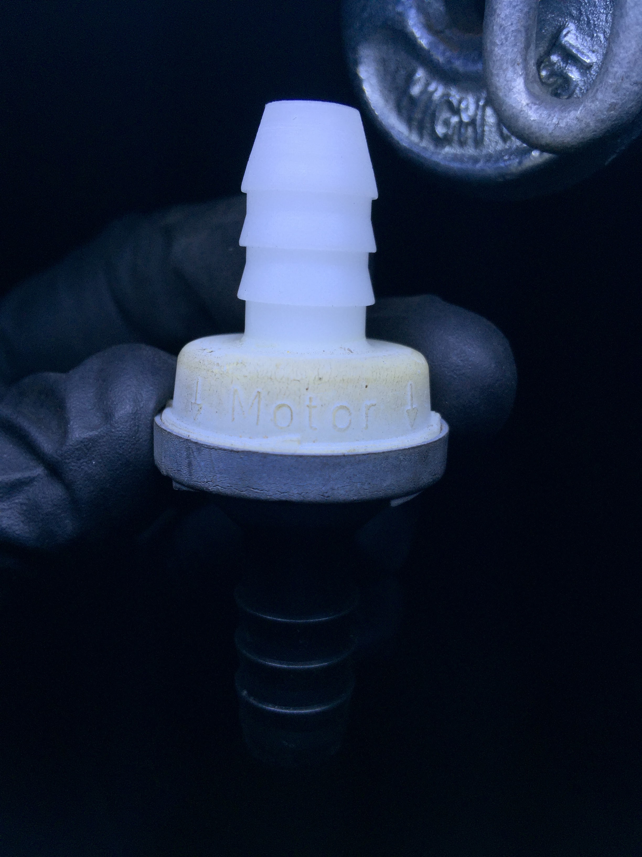
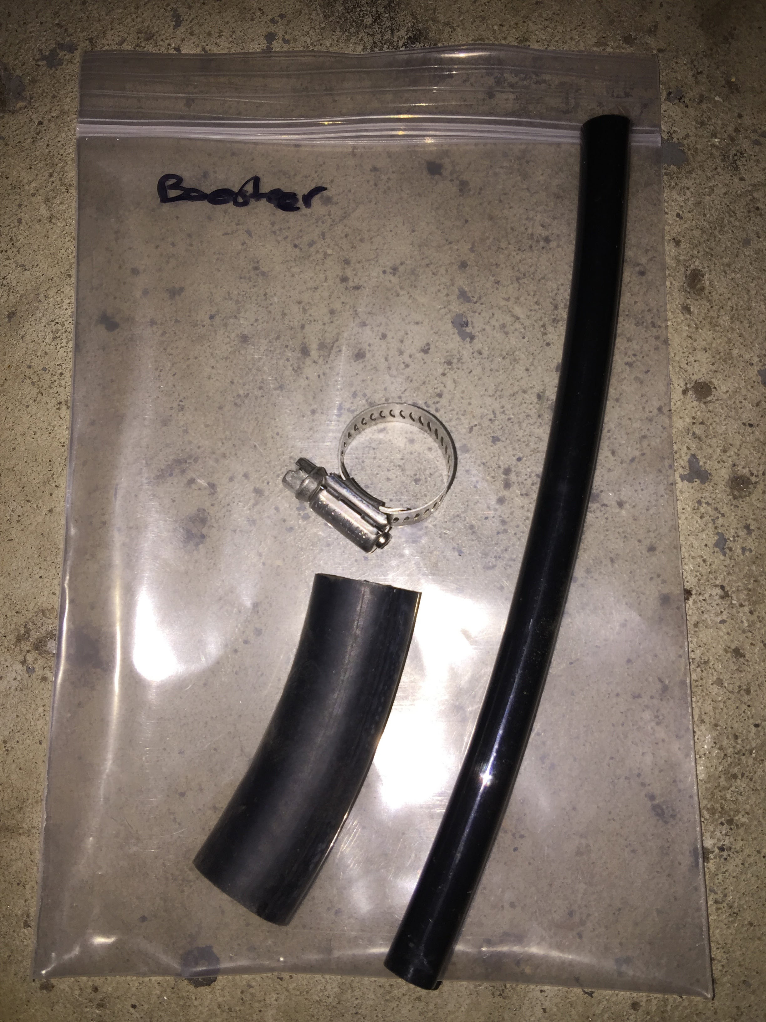
After this first drive, two vacuum leaks were discovered and eventually tracked down. The first one was pretty obvious, as there was a loud hissing sound that was hard to miss. It was on the emissions hose running from the IAC to the PCV valve. After removing some kind of protective foam that the hose was wrapped in, I tightly re-wrapped it with electrical tape as a stop-gap while I waited for the new part in the mail. Leak fixed. The new part also included a smaller elbow piece that connects to the PCV valve that's located on the exhaust side.


The second one was a little trickier to locate. I used an extra piece of coolant hose as a stethoscope-like device to track this down by listening for leaks. With the engine running, I simply put one end of the hose up to my ear, and then ran the other end over and around the vacuum hoses. It worked amazingly well. A leak was eventually pin-pointed at the brake booster check-valve connection. My kit only came with one clamp, whether by design or accident I'm not sure. A second clamp had it fixed in no time.
And remember, unbeknownst to us, all this time the brand new FLAPS IAC was giving us wonky RPM readings. Luckily this was the least of our concerns, so even though not perfect we were able to move forward in testing. The van drove "fine", there would just be some hang-ups and/or spikes in the RPMs, especially when shifting.
After the two vacuum leaks were fixed, there was yet another marked improvement in performance. After yet another short drive, getting things up to temp, and sending in another large datalog, fixing those two leaks was essentially the final issue to get me on the road! This was good, as my time in the borrowed garage was quickly nearing its end. I was given the "OK" to make the 15-minute drive home!
Finished
That's pretty much all she wrote! The drive home was uneventful yet exhilarating at the same time. Here's a few parting pics.


Better take a picture before you leave, it will NOT stay clean for long! Haha.
Considering it took me over a year to get this post up after Part 1, we have already put some pretty good miles on our newly Bostig-converted van. Head on over to our Bostig Review to see the pros and cons and our two-cents on the overall process.