Instrument Cluster Foil Repair
Supplies Needed:

Cheaper than the competition AND it’s easier to install!
Fix the old blue foil in your Vanagon dash for good! Also called "printed circuit board foils" or "PCB foils", our kits are a rock-solid modern replacement with push-pin and eyelet installation; it could not be easier!
We have been selling and supporting these kits for over 10 years now…that’s right, TEN years. These work. Period.
Fits all Vanagons 1980 - 1991. See below for full product description.
Tools Needed:
Phillips-head screwdriver and/or a 6 mm and 7 mm socket driver for screws
Flat-head screwdriver
Electrical tape
Skill Level: Easy / Moderate
Before starting, please read our Disclaimer. By using this website you agree to these terms.
Comments:
There is a printed circuit board (commonly called "blue foil") behind your instrument cluster that ties everything together including the cluster lights, clock, gauges, and indicators. You'll know this blue foil has failed when lights and/or gauges stop working. Installation will take approximately 1-hour.
It is very important that you work gently throughout the process. The instrument cluster is made of plastic that's now 30 years old. Depending on it's condition it can be very brittle and/or fragile to work with. Suffice to say, you don't want to break any part of the housing, screw holes, etc. The blue foil is getting replaced but all other parts of the cluster will be reused; this includes the screws, nuts, and washers that hold the foil in place. Do not throw anything away until you have verified the installation is working properly!
The steps below are specifically for the CMBA kit. However, the CMA and CMBDT kits are very similar and are even easier to install as they have no extra wires to secure. (You'll learn about the extra wires below.)
IMPORTANT DISCLAIMER: Failure to follow the below instructions could cause an electrical short, fire, or instrument malfunction / damage. We are not responsible for incorrect installation and all guarantees will be rendered void. If you have any doubts stop what you are doing and contact a certified mechanic.
Instructions
You can see Cluster Master’s (they make the kits) official install video below. If you prefer pictures and text, keep scrolling down the page for a step-by-step guide.
Step 1:
Disconnect your battery!

Step 2:
Remove the cluster cover. There are two large indentations on the back of the cover. Pull up. Be gentle, but at the same time you will need to pull much harder than you might think. Once the cover is off, there may or may not be a protective plastic sheet remaining. Set both the hard cover and the soft plastic sheet aside in a safe place.


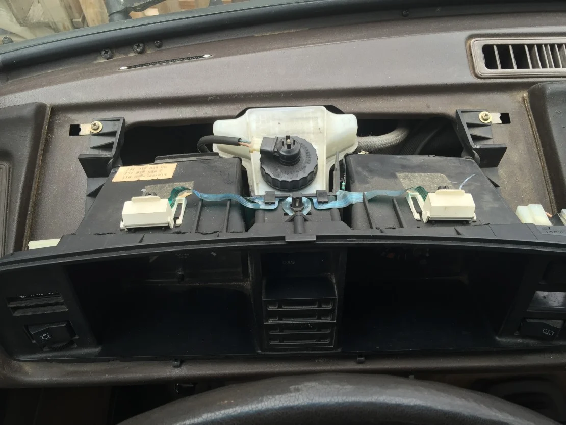
Step 3:
Remove the instrument cluster. There are four (4) screws, one at each corner. You will also need to detach all switches or plug connections. Be sure to work gently when pulling. I always take the easiest route when disconnecting the plugs. Most of the time the entire switch will come out easier than actually unplugging the wires from the switch. However, if it unplugs easier that is fine too.
There's also the speedometer plug which either screws on or has squeeze tabs to release. Lastly, the wide, main harness plug.


Step 4:
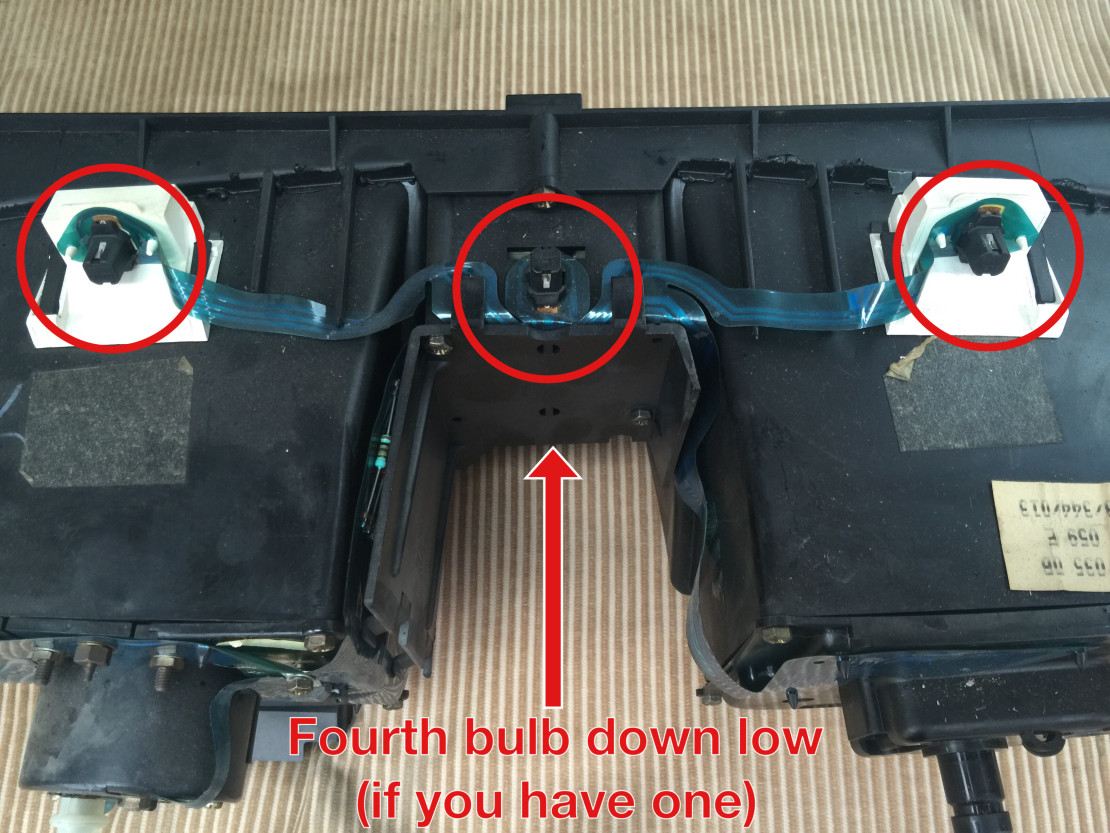
We can begin removing the old blue foil! First start with the light bulbs. There's three on top, and if you have a digital clock, there is a fourth bulb to remove for it. These are removed by twisting 90 degrees to the left. You may be able to turn them by hand, but if not, use a pair of pliers to gently turn.


Step 5:
Starting on the left side, remove the screws and nuts that hold the blue foil in place. The white plastic piece is removed by simply pulling up. Most of the screws are dual-function in that you can use a phillips-head screwdriver or a hex socket (6 mm or 7 mm).


Step 6:
Remove the center LED cover.


Step 7:
Remove the plastic clamp on the main connector.


Step 8:
Remove the blue foil. At this point most of the foil may simply be falling off on its own. If not, the only things holding it on are little plastic spurs. Gently pry using a flat-head screwdriver to remove any last connections. There is also usually some tape holding the middle foil in place; gently peel this off.


Step 9:
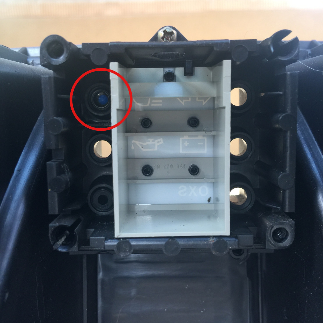
Remove the blue cap for the old high-beam indicator. This must be removed to make room for the new LED that will take its place. You can sometimes pluck it out by gently using needle-nose pliers. If this won't work, remove the one screw holding the housing in place and push it out from the front. Once done, re-install the housing.


Step 10:
Removal is complete and you are now ready to install the new kit! You've heard of "paint by numbers", right? Well, this is "wire by numbers". (I know, technically letters.) Looking at the diagrams below, choose the proper layout for your cluster. (NOTE: These diagrams show the BACK of your cluster.) Then, simply match the wires to the corresponding letter and attach as needed. If something seems complicated you're most likely overthinking it. (Or you ended up with the wrong kit.) Plug-and-play is the name of the game here.
In this example we need the CMAH diagram. Each diagram can be enlarged by clicking on it, giving you an easy to read view.
For all five layouts the bulk of the wiring happens on the left side, so this is where we'll start. Working from the inside-out makes the routing easier, in my opinion. That means for the CMA, CMAH, and CMBA kits we start with the "C" wires, then B, A, and D wires. The CMDT and CMBDT kits can simply install alphabetically, A - D.
To connect the eyelets, reuse the washers and nuts you removed earlier. When tightening, snug is all you need. DO NOT OVER TIGHTEN. Again, work gently.
Remember, this example is for the CMAH kit. Please use the appropriate diagram for your kit!


Step 11:
IMPORTANT UPDATE:
We now offer fully plug-and-play kits for ALL clusters. This means every wire will have a connection. NO kit will have bare ends like shown below.
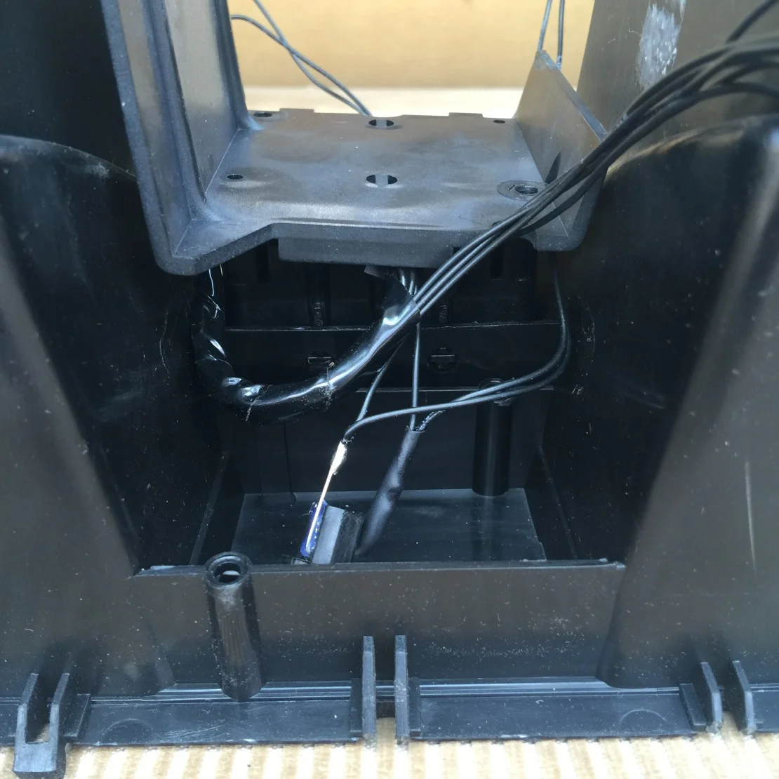
Next up are the P and Q wires. These two bare wires are what set apart the CMAH kit from the others. Don't worry, they are still easy to attach.
Secure the Q wire under the screw by wrapping in a clockwise fashion. This will ensure the wrapped wire stays secure when you tighten the screw. You'll know if you've wrapped it the wrong way as it will begin to unwind from the screw.
For wire P, simply fold the wire over the metal tab and then secure it in place with the white plastic holder.


Step 12:
Insert the new illumination lamps. Gently twist in place the same way you removed the old ones.


Step 13:
Install the new LED cluster. Should be pretty self explanatory where these go.
NOTE: All kits appear to have a clear LED instead of a blue one for the high beams. Don't worry! It will indeed be a blue light when you turn it on.
You can use a couple of small pieces of electrical tape to hold them in place, if desired. Just make sure you don't block any holes that are needed to re-mount the cover.


Step 14:
IMPORTANT UPDATE:
We now offer fully plug-and-play kits for ALL clusters. This means every wire will have a connection. Do NOT tape over wires as shown below. We are working on new documentation to reflect our new offerings. If you have any extra wires that likely means you ordered the wrong kit and will need to exchange it for a different one. All other instructions below still apply. Simply ignore any instruction to tape over unused wires.
The only connections left are for the tachometer and the oil buzzer. If your cluster has these connect them now. This cluster does not have them.


Step 15:
Replace the cover for the center LED cluster. There is a certain amount "squishing" here, so take your time and make sure nothing gets pinched or crushed! The end result should look something similar to this.


Step 16:
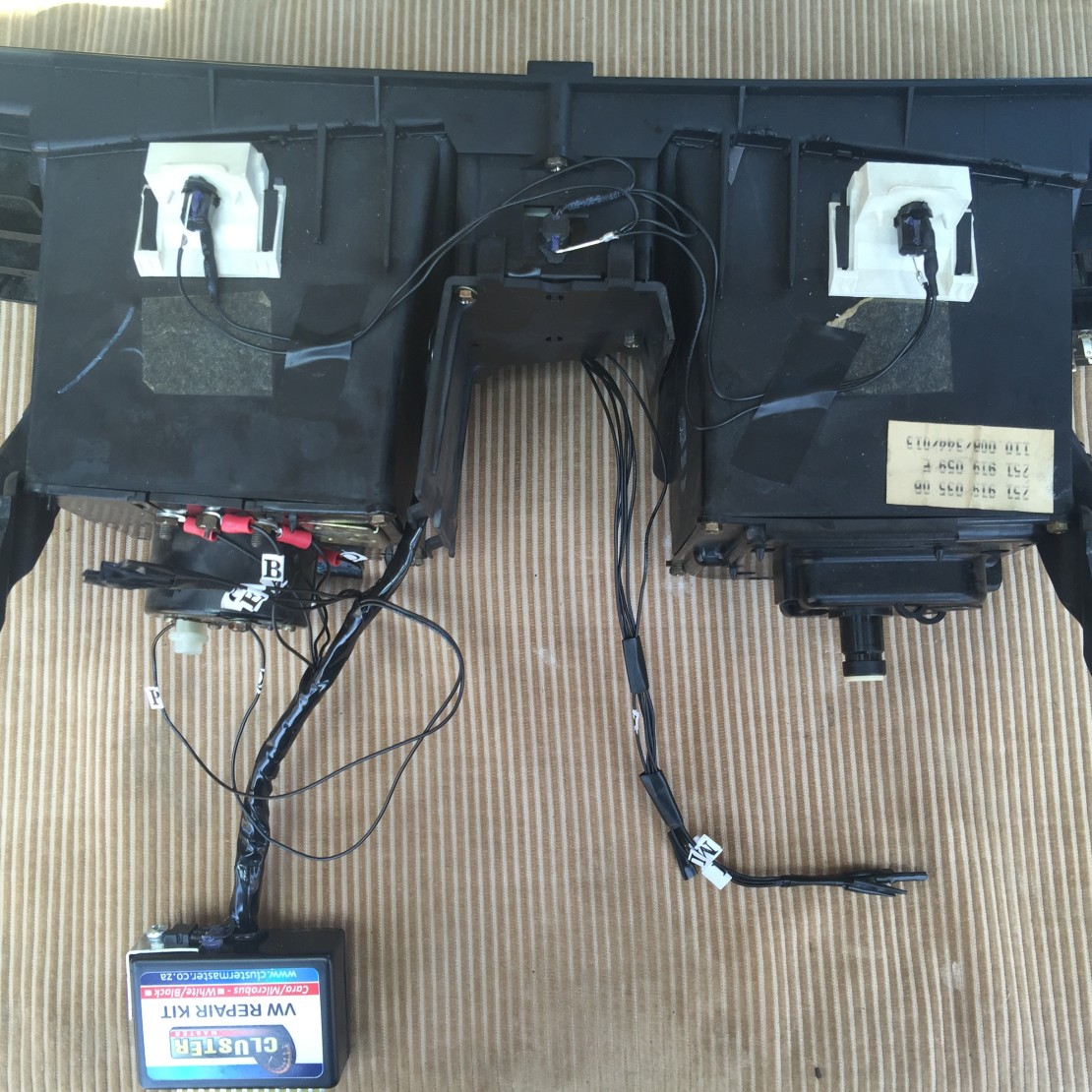
Clean-up and organize. Bundle together the groups of wires to help secure them in place as a whole. Then, tape the bundles to the cluster in a safe area. Not much more here to say besides look at the pictures to compare. Make sure nothing is flopping around loosely. For this CMAH kit, in particular, take notice of wires P and Q, as they will likely be much longer than needed. Tape the slack to the main wiring harness.
Also, don't forget you removed a couple of screws that held the old blue foil in place that ALSO hold the back of the cluster together. You will obviously need to reinstall these!


Step 17:
Test your kit! Temporarily re-install the cluster into the van; do not secure it to the dash with the screws yet. While installing, double-check that all wires have proper clearance and routing, with nothing getting pinched.
The Cluster Master connector has numbers on it, match these numbers to the van's main harness connector.


With the cluster cover still off, reconnect the battery. Turn the key to the "ON" position. These lights will come on (if you have them):
Battery - steady
Oil - steady if no buzzer, flashing if you have a buzzer
OXS - steady
Coolant Level - flashing
If everything checks out, start the van. After a few seconds all of the above lights should turn off. If not, please see the "Trouble-shooting" section below.
If they do turn off, great! Make sure the high beams and turn signals work too. If they do, you're good to go.
Step 18:
Once you have verified everything is functional, turn the van off and disconnect the battery again.
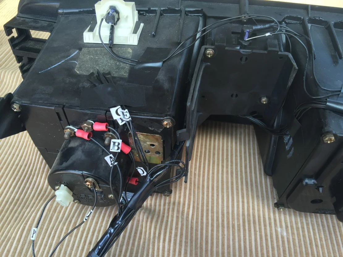
Your kit includes zip ties to hold the connection together. The plug should stay together under its own tension, however, YOU STILL MUST ZIP TIE THEM TOGETHER. The new connector is different, as it is not secured directly to the cluster like the original VW design. The zip ties give an extra layer of insurance so the plug will not wiggle loose when you're bouncing down the road.
NOTE: Your zip tie placement pretty much needs to be identical to the below pictures.
It is crucial that you do not over tighten the zip tie and pinch a wire. Also, NEVER secure the zip tie around the voltage regulator. (The metal piece on the left.)
Secure the cluster to the dash with screws you removed earlier.
Install the main cover, reconnect the battery one final time, and you're done!


Here's a short video of the finished product:
Trouble-Shooting
Before you start, disconnect your battery!
Rarely you will run into problems if you have followed all of the above instructions. However, nothing is perfect, we are all human. If something is not working you almost certainly have a loose connection somewhere. I cannot emphasize this enough. The vast majority of problems will be fixed by re-checking that your connections are snug.
First double-check the connections on the back of the cluster that you just installed, as this is the easiest solution. If that doesn't remedy the problem, move on to the main connector.
Verify 14-pin Connector
Occasionally the 14-pin main connector on the van-side is abnormally loose / distorted. Don't worry, the fix is easy. These pins simply need to be re-positioned and/or re-tensioned so they make proper contact with the board on the new kit. The female plug (usually white, sometimes black) pops open, which then allows you to assess the pins. Here's some pictures to walk you through the process:
Step 1
Notice how the metal pins / springs on the inside of this connector are barely protruding above the plastic housing.

Gently pry open the door on the plastic housing. Only about the top third opens.


Step 2
Pull out each pin one at a time so you don't forget where it goes! If you can take a picture of everything before you start that would not be the worst idea.
Using a paperclip or something similarly small, gently bend the springs up. Do not go crazy here, as you certainly do not want to over-tension them and break something off. You're just moving things one or two millimeters higher. Compare the first and last pictures below of how far to bend. Note, these pics are zoomed-in. In reality all of this is very small in your hand.


In the picture below, you can see the first and last pins have been re-tensioned. The left-most pins are at the maximum level (arguably past) of tension, definitely do NOT go any farther than that. The right-most pins are just about perfect.

Step 3
Once you're done with all of the pins, make sure everything is re-seated properly inside the housing. If you look at the back you should be able to see how far all of the pins are seated.

Close the door and reconnect the plug to your new kit, making sure you match the numbers on the plug to the numbers on the kit.


After verifying everything works, make sure and zip tie the plug together as shown in Step 18 above.
Do NOT send yourself on a wild goose-chase checking other sensors, wires, etc., until you have absolutely, 100%, verified proper contact. This kit is simple. If something is not working, almost certainly the fix will be simple. Do not over-think the process!
Other Trouble-Shooting
By far, the above issues of verifying proper connections will solve the vast majority of problems. Here are some other, less common issues we have seen.
PLEASE NOTE: These solutions are based on feedback from customers who had van-side issues.
***None of these problems are related to the new replacement kit itself.***
We will gladly help verify that your kit is working properly (FYI, it’s EXTREMELY rare the kit is at fault).
Your old foil may have been hiding much deeper problems than simply not illuminating a bulb on your dash. We can give generic advice for trouble-shooting these issues, but we cannot give support beyond that, as each van will have its own issues that are simply too hard to diagnose remotely.
I cannot emphasize enough that we are unable to help trouble-shoot van-side issues beyond what you see here. We would love to be able to help resolve any and all issues, but it’s not practical and it’s not fair. Not only is it almost impossible to do a thorough diagnosis remotely, a service like that goes far above and beyond what this kit is advertised to fix.
With all of that being said, please contact us if none of the above or below gets you straightened out. Again, every scenario is unique, so it can’t hurt to run things past a new set of eyes. There may be something simple that is being overlooked.
Dash lights seem dim
Make sure your dimmer switch is functioning properly.
Proper grounding
After checking the dimmer switch and your cluster lights still seem dim, you almost certainly have a grounding issue on the van-side of the wiring.
Also, the opposite can be true; if you have a light that will not turn OFF (e.g., the high-beam indicator) a bad ground is very likely the cause.
When you see symptoms like these it means the electrical current is being disrupted somewhere. There is a large grounding tree under the driver-side dash near/behind the fuse box. Clean any and all corrosion and check for proper connections.
High-beam indicator remains on
Check for proper grounding in general (see above).
Make sure the headlights themselves are properly grounded and/or have solid connections. We have seen this problem a few times now.
Battery light remains on
Unplug the cluster immediately or you run the risk of damaging the kit! When the battery/charge LED doesn't switch off, it says that there's a charging circuit problem. This particular circuit WILL damage the kit if you do not address the issue.
Something somewhere in the charging system isn’t working properly. You, or a qualified mechanic, will need to trouble-shoot the various components to locate the problem.
If a gauge used to work and now doesn't
Make sure there is no physical obstruction preventing movement. By now your cluster is old and the plastic housing can commonly have small pieces of broken plastic floating around in it. During the install you are moving the cluster around in many different ways, this may cause a piece of plastic to become lodged in a gauge preventing it from moving properly.
In much more rare cases, internal components can fail in a gauge. So far we have seen two instances with this:
The pins for the oil buzzer are mounted on an L-shaped PCB. This board can become corroded or damaged and cause issues. Cleaning it and/or re-soldering the joints will fix the problem.
The pins for the tachometer are mounted in a similar fashion. Again, cleaning and/or re-soldering the joints will fix the issue.
If you have verified all of the above and it still doesn't work please contact us.