Bostig Installation – Part 1
The time has arrived, our Bostig engine conversion is going in! Part 1 will primarily cover engine prep and the removal of the old Waterboxer engine. To see more of the installation side of the project, be sure to check out Bostig Installation - Part 2. You can read about why we chose Bostig over here.
NOTE: This article is NOT intended to be a step-by-step guide like some of our other posts are. It's purpose is to show the overall process of the Bostig engine conversion.
I'm very much a visual learner, so you'll see pictures of almost everything. I feel this is one area the manual could use improvement on, i.e., more of them. As they say, a picture is worth a thousand words, and this couldn't be more true for me. One pic can usually show me what to do better than a paragraph of text, so hopefully other visual learners can learn something from this.
If you have a specific area of interest use these links to page-jump to the appropriate topic:
SKILL LEVEL: Moderate / Difficult
Before starting, please read our Disclaimer. By using this website you agree to these terms.
Picking Up the Zetec
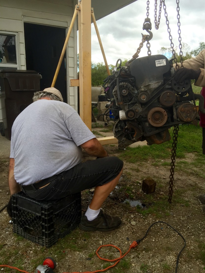
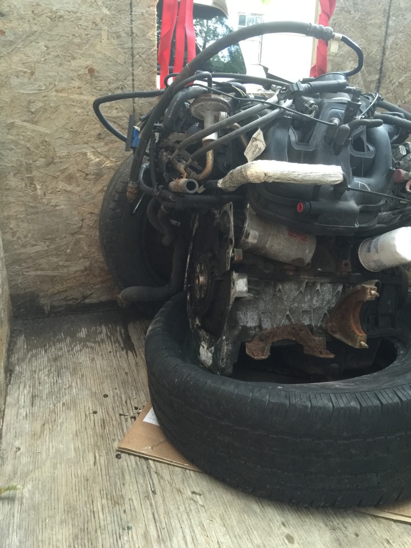
We technically started our conversion on September 19, 2015 - the day we picked up the engine. I scored a great deal on Craigslist from a retired mechanic named Al; just $100 bucks for the engine with only 42,688 miles. I picked it up using our trailer, two tires for cushioning, a piece of cardboard to help slide it around, and two straps to secure everything. Notice how I positioned the weight to be on the exhaust side of the engine. The intake side is made of plastic and likely would be damaged if shipped on that side.


In hindsight, I should have picked up an engine much sooner. We had committed to the Bostig months earlier, but I didn't even really start looking until most of the Bostig parts were in-hand. I could have "saved" myself a lot of time by working on engine prep stuff before the Bostig parts started showing up.
Identifying Parts on the Zetec
The first thing I did was go through Bostig's engine prep video (embedded below) and ditched all of the unwanted parts.
TIP: You should watch this video BEFORE you go pickup your engine or have it delivered. I did not do this and really wish I had. Having only minimal DIY mechanic experience I knew some basic stuff, but there was a lot that I was clueless on. It would have saved me a bunch of worrying had I watched this video first.
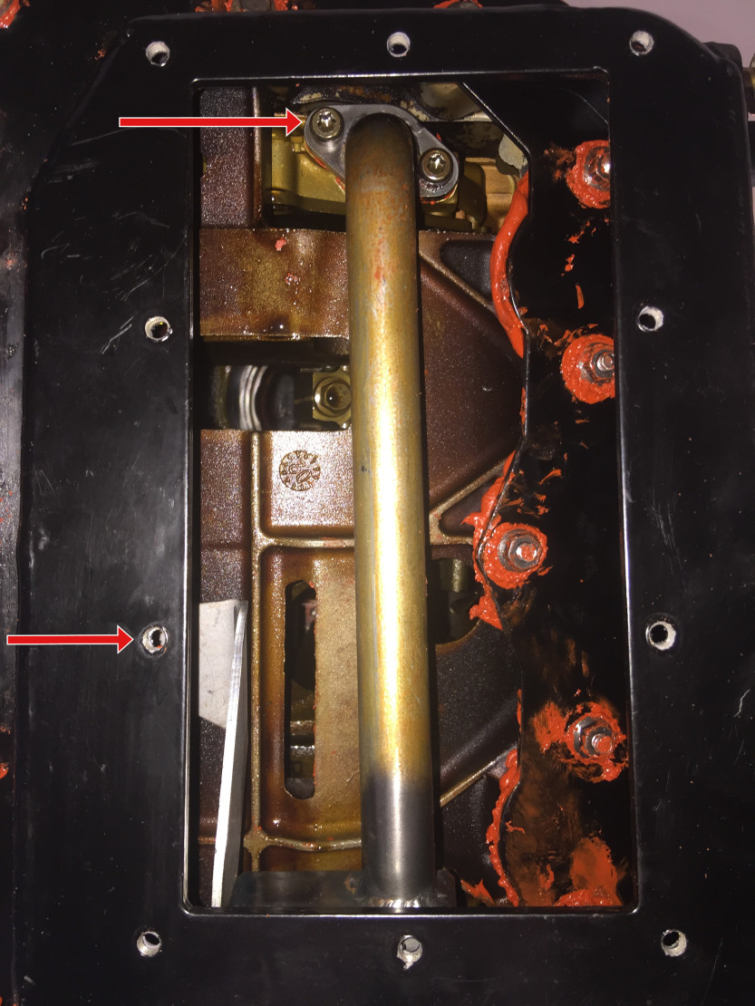
The video is great, but it was clearly made a few years ago and is not HD, making some parts hard to see. I didn't know what everything was called at first, so here are some pics I marked up to hopefully help out the next person:


Crankshaft Endplay
After lots of cleaning and double-checking I finally moved on. Next up was checking the crankshaft endplay.


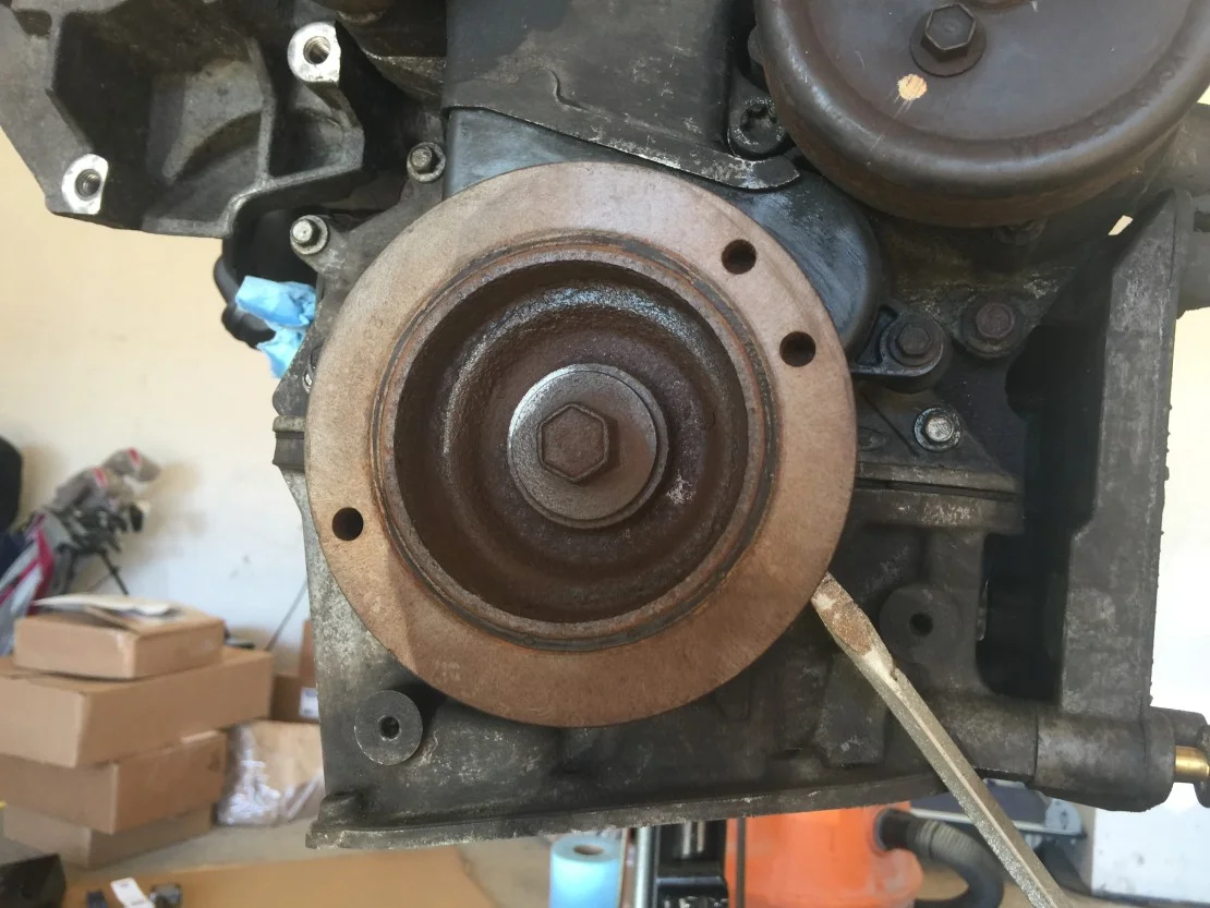

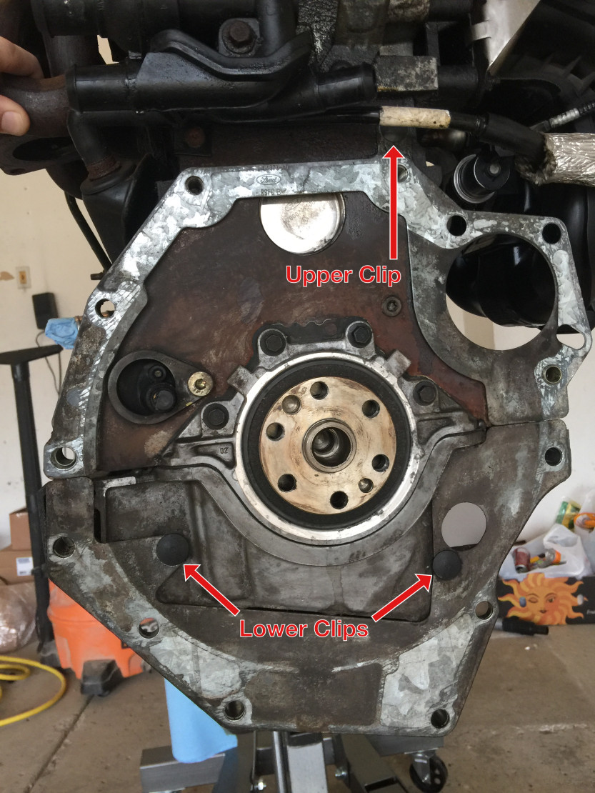
SK-A (Adaptor), Removing Shims
Started working on the first sub-kit, SK-A. First, removing the engine shims. (It's always the simple things that cause me the most trouble!) The lower shim has two black retaining clips. Not knowing how these simple clips worked caused me to break one of them. There is a small pin that goes through the center of the clip to lock it into place. You need to push this pin out by using something very small. A ⅛ inch drill bit perfectly fits through the hole, so something at least that small will do the trick.
The upper shim just has one clip and could be pried out by pulling gently on the shim itself.


I later realized it's not a big deal that I broke one of the clips. I wish someone would have told me this, as I spent a fair amount of time finding a replacement! The clips are simply used to temporarily hold the shims in place. When you later attach the adaptor plate, the bolts you use go through the adaptor plate and the shims, rendering the shims obsolete. I eventually removed my new replacement clip since it didn't match the old one exactly.
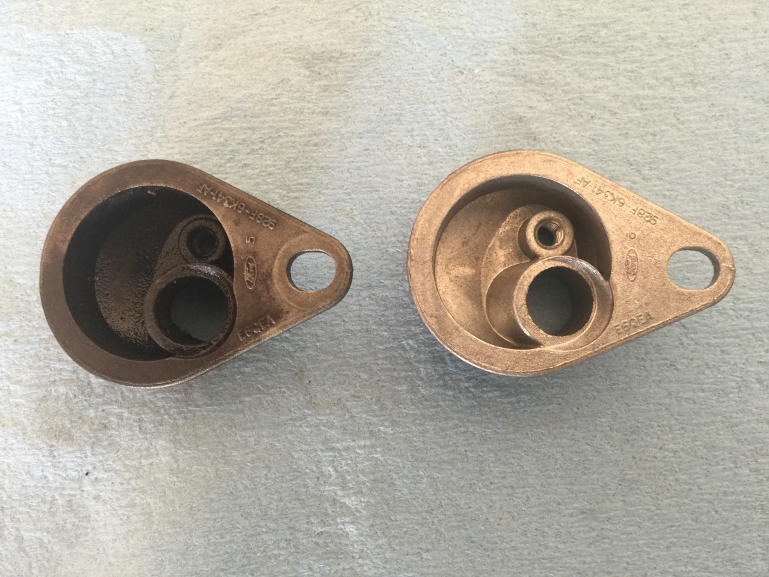
Crankshaft Position Sensor (CPS)
Next up was the crankshaft position sensor (CPS) and associated cup. You MUST replace the cup prior to installing the adaptor plate and flywheel. You will NOT be able to access this later if you forget.


New Bostig shims, pilot bearing, Adaptor plate


The bolts on the adaptor plate had to be shimmed out with some washers. After another trip to the store, they are now at the proper depth, i.e., they do not protrude above the surface. Considering all of our bolts except for one had to be shimmed, I would recommend picking up some extra washers before you do this.


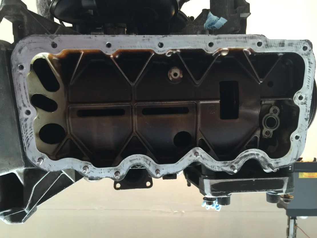
High Capacity Oil Pan (HCOP)
UPDATE: August 2019
I strongly recommend using this pre-cut gasket (also pictured below) made for your Zetec engine. This will allow you to bypass the messy and unforgiving RTV / Right Stuff gasket maker. You will still need some RTV for the access panel (or cut a custom one like this) and pickup tube, but this cut gasket takes the bulk of the mess and worry out of the equation.

Here’s why…we ultimately developed an oil leak 2.5 - 3 years after installation. This is pretty common, unfortunately. We are far from the only ones have this happen. Long story short, we had to re-do the HCOP gasket and used this the second time around. SO MUCH BETTER. Low-stress installation with no worry of the RTV curing too quickly or not making a good seal. Some people on the internet recommend using a liquid sealant on top of the cut gasket, but we installed it dry and torqued to spec. As of this writing it’s been 3.5 months and we haven’t leaked a drop! (This is also the third oil pan gasket in general we’ve installed dry. None of them have ever leaked.)
Also, I figured out how to easily reach the back few bolts…just find someone with small hands to do it, ha! My wife (5’4”, slim build) could very easily reach inside and assemble everything. Amazing!
I have a bunch of pictures I plan on adding to this post, but wanted to make a quick note for now. See below for the original post. Just remember, wherever you see the red RTV you could be using this nice cut gasket instead. (Except for the smaller access panel and pickup tube.) No mess, no stress!
Oh woe, yee, High Capacity Oil Pan (HCOP). In hindsight, I spent WAY too much time researching and reading up on this; I had heard many people say it's a huge hassle. Well, they're right, except it's only a hassle due to fitting your hand into a tight space. The overall process is very easy:
Install the seven studs.
Apply RTV for the main oil pan.
Install the main pan.
Apply RTV to the top connection of oil pickup tube.
Install pickup tube.
Adjust the dipstick so it does not interfere with the pickup tube. i.e., it doesn't hit it. If you ordered Bostig's heat shield (EDIT: This is no longer offered.) it would be a good idea to size this up at the same time. The dipstick gets repositioned for both of these. (This can be done later if you forget, it's just harder to do by feel.)
Apply RTV for access panel.
Install access panel.
One of the more confusing parts for me was simply understanding the terms used in the Bostig manual. The "oil return drain / turbo drain" really threw me off because I didn't have a turbo. It seems so simple now, but you don't know what you don't know, and with no diagram or picture labeling everything I was clueless. A simple picture like this would have been great:

This is one area where I did not follow Bostig's manual. I did not like the work time of only five minutes for The Right Stuff that Bostig recommends to use; just seems like I've read about too many people having trouble with the short work time. Knowing my workflow, I did not trust myself to get it done in just five minutes. After reading this person's write-up (on Bostig's support site) it only confirmed my thinking. By using his recommended High-Temp Red RTV you get one hour of work time. I also considered the Ultra Black RTV. They are all essentially the same except that The Right Stuff is fast setting and can be used almost immediately. (They're all made by the same company, cover roughly the same temp range, and all claim to be OEM.) I chose the Red RTV because:
I wanted more than five minutes of work time.
The person above seemed similar to me and had success with it.
I liked the red color; shows up nicely in pictures. :)
Another area where I ended up going against the usual consensus was by NOT using an engine stand. Many people basically claimed it was gospel to use an engine stand for the fitting; this will allow you to flip the engine upside down, therefore making the job easier. This is simply not true, at least it wasn't for me/us. I started to go down this route; had the engine on the stand, flipped it over and was ready to go. However, it's a very tight fit to get my hand in there...what would happen if I dropped a nut/bolt into the engine? It seemed like a very real scenario for me. (What can go wrong will go wrong, almost always.) So I ended up ditching the engine stand and going back to the engine hoist. (Easily wasting a couple of hours in the process, not to mention the time and money spent buying the stand in the first place.) I had a nice creeper I could use to lay on and work on my back. It just seemed like any inconvenience by working on my back was worth it versus the risk of dropping stuff into the engine.
I'm happy with the route I took. Took me about two hours with spending an hour and a half on the last couple of bolts. I must have dropped those last two fasteners and/or wrench at least 30 times combined, especially the one in the tightest space. I literally could not fit my hand in there to get it started, hence my previously mentioned worries. After what seemed liked forever of trying to get the last one, my saving grace was my friend happened to be home (I'm using his garage) and he had smaller hands to just get the job done. (He had no problem working on his back either.) Otherwise, I would have left it uninstalled and hoped for the best; that obviously did not seem like an ideal solution, but, I would have had no choice.
For the record I wear XL gloves and can palm a basketball. My hands are large, but not abnormally large, just above average. My friend had more average sized hands and could just barely make it work.
I now see what the manual means when it says to do a practice run. They mean to do it all the way through. I took it as a way to understand the whole process, which in hindsight was a mistake. It wasn't until I had applied the RTV that I realized I couldn't reach the last bolt. Not sure if it would have changed much though. At this point I was committed to doing it.
I understand engineering takes time and money, but I see two ways this install could be made much more user friendly:
Simply sacrifice a few cubic inches of internal space and move the last two bolts to the outside.
Make the access panel larger, i.e., go all the way across.
Or both.


The last hangup for me was installing the new oil pickup tube. Two out of the three bolts were unreachable for me, though I probably could have gotten the one eventually. Even my friend had trouble with the most difficult one, we eventually made a run to the store and engineered a flatter wrench to get into the tight space.
The last steps were the access panel and the turbo drain plug; finally something easy! I did it by myself but a second hand would have been nice, at least in the beginning just to hold it in place.


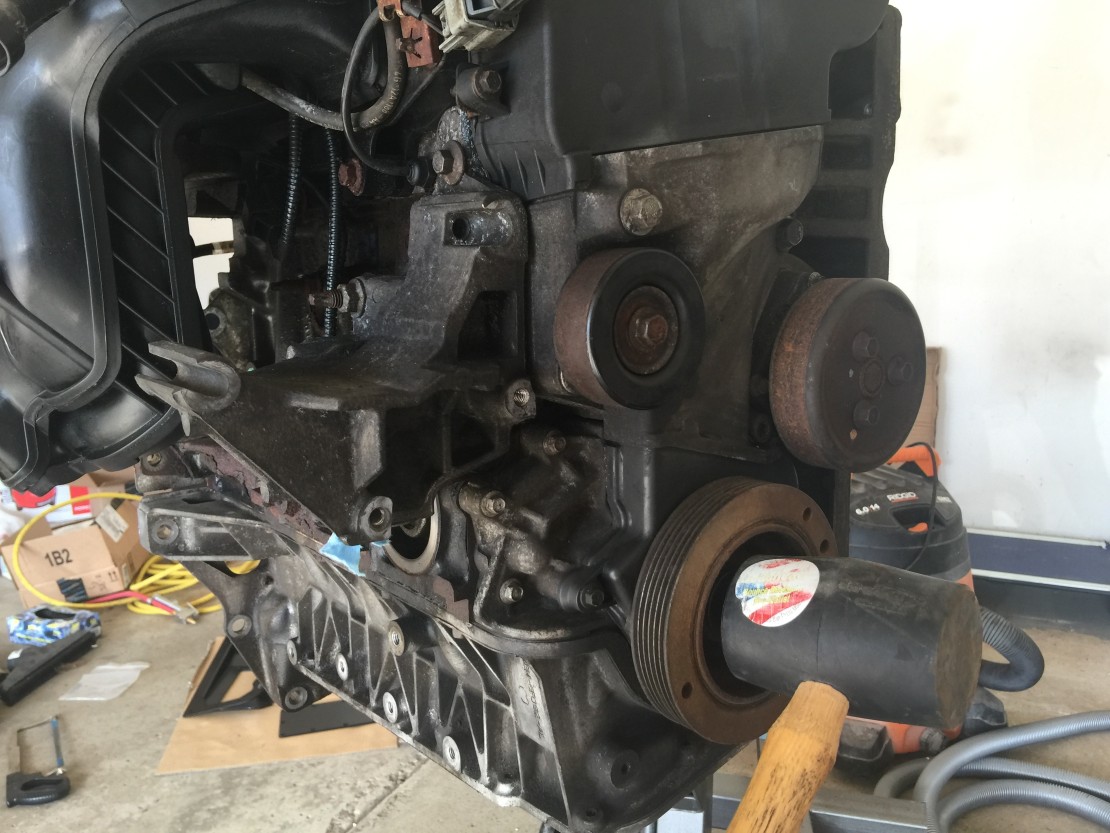
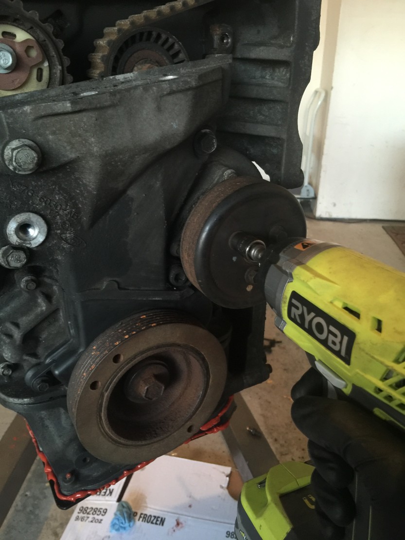
Timing Belt and Pulleys, Water Pump, Check Cam Timing
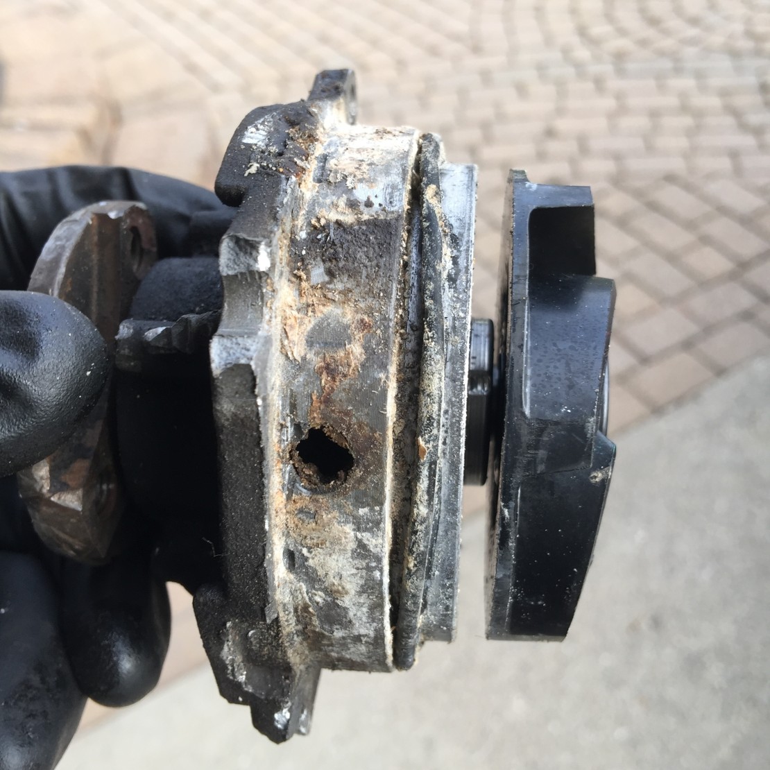
New timing belt, tensioner pulley, idler pulley, and water pump. The water pump was a bear to remove! So glad I replaced this before the engine was installed. Lots of prying and hitting with a rubber mallet. Just make sure you don't damage the engine-side of the housing!


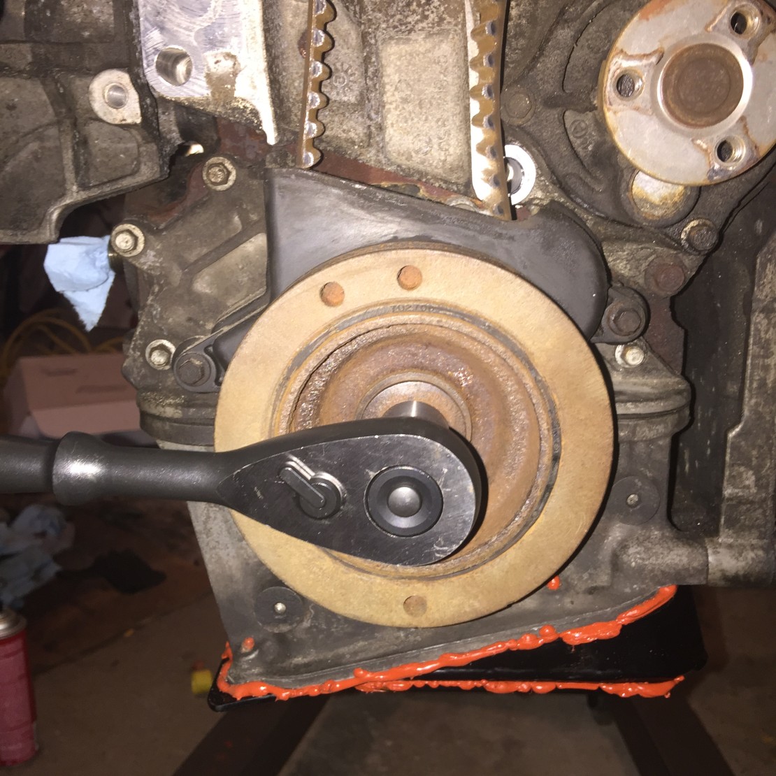

Cam Timing
Set the timing. Two important things that could have helped me immensely:
The timing bar will likely be a very snug fit into the cam shaft slots. I thought it would easily slide in and out. This misunderstanding cost me hours of work trying to make it fit perfect.
You will almost certainly need multiple vise grips to adjust each cam shaft. I needed three: one to do the adjusting, and two more to secure the cam shaft from spinning left or right. Something (the valves) kept making the cams shift unexpectedly. I only had one vise grip when I started, now I have four.
In hindsight, I now wonder if my original timing was good enough. I thought the timing bar would easily/loosely fit in the two slots, I did not realize I might need to gently force it in ending up with a very snug/tight fit. Oh well, I'm sure it was easier to learn the ropes with the engine out of the van rather than being installed. I do think I ultimately have a better timed engine now, albeit, by a small margin. If you're doing this for the very first time it will likely take you all day to do the timing and change out the timing belt and pulleys. It took me eight hours to do everything, with about six spent on the cam timing alone. I kind of ramble on in the video below, sorry, but it was the end of a long day to say the least.
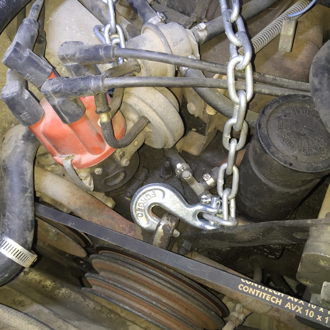
Waterboxer (WBX) ground clearance
Taking some measurements to compare ground clearance later.


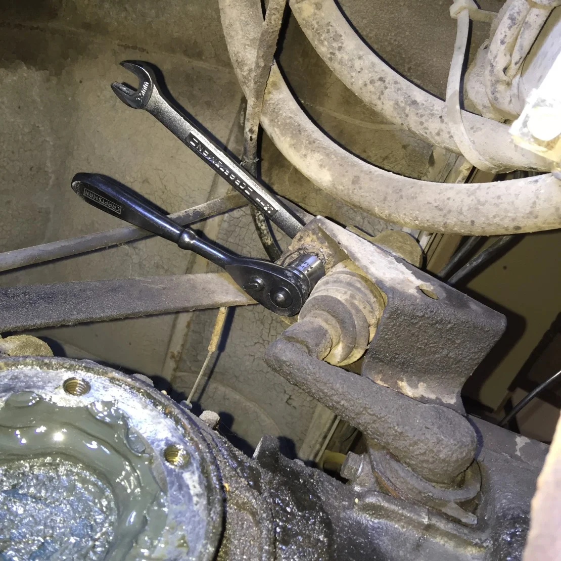
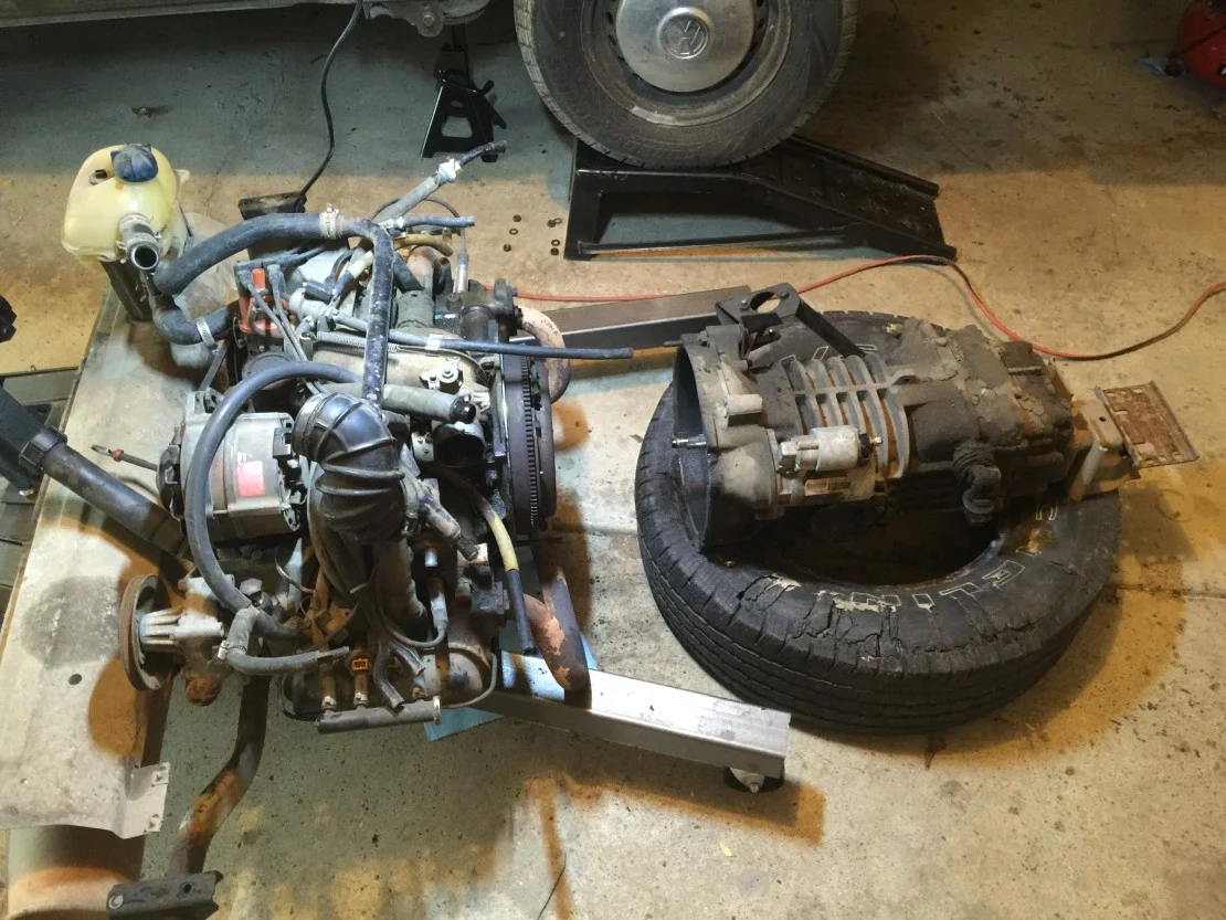
WBX and transaxle removal
A major milestone, out with the Waterboxer and transaxle!


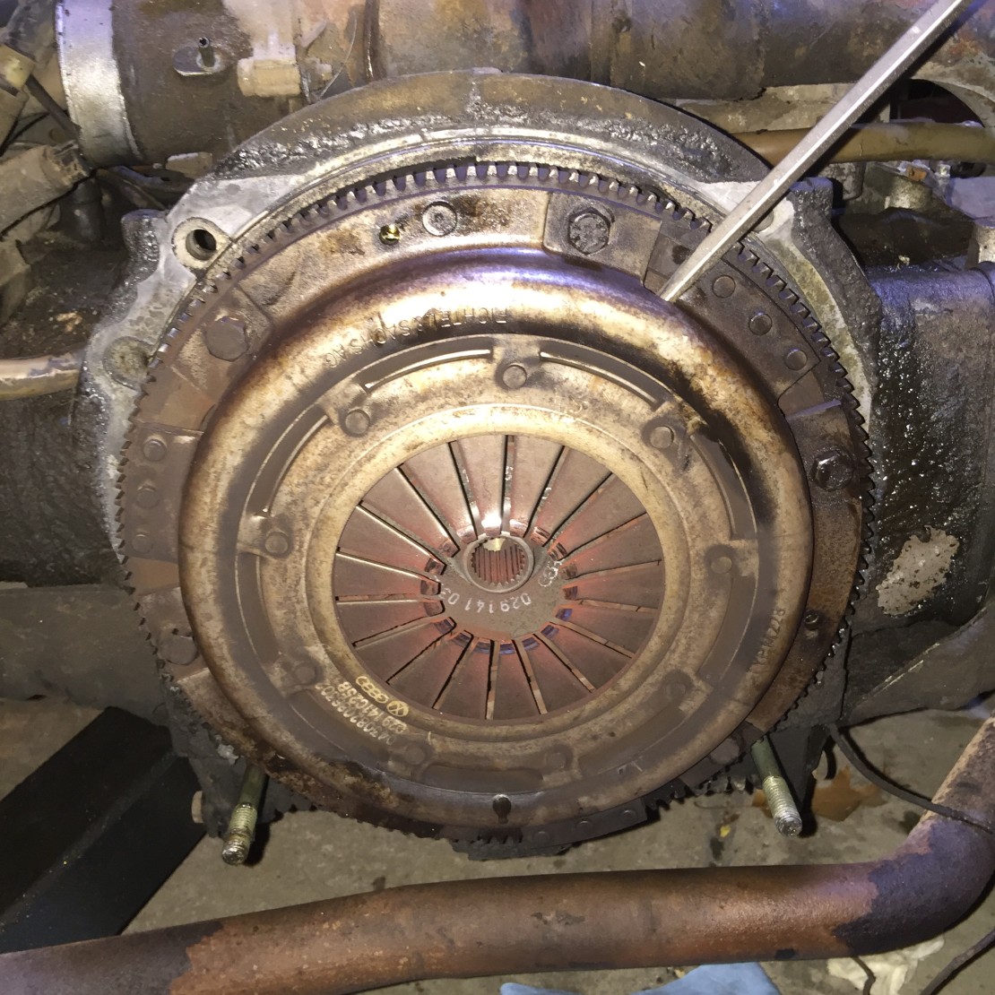
Roll Pins and Flywheel
Roll pins. The manual breezes right past these like they're no big deal. I guess in a way they aren't, but we had no idea what they looked like. To make matters worse, try Googling "Vanagon roll pins" and you get nothing of substance. Also, if you literally follow as the manual reads, you'll end up marking the depth and pulling the pins before you remove the pressure plate. Don't do this. Remove the pressure plate then mark the depth and pull them out.
Another mistake I made was that I marked the depth with the pressure plate still in place, but then transferred them to the new flywheel before attaching the new pressure plate. This made the pins too deep. Luckily I caught my mistake and it's really not that big of a deal. I spent some time trying to pull them out a little but then realized it was ok that they were "too deep". They just need to stick up far enough to align the pressure plate. They're simply used for alignment, they don't hold anything in place long term. I know, simple now, but you don't know what you don't know.


Clutch and release bearing (a.k.a., throwout bearing)
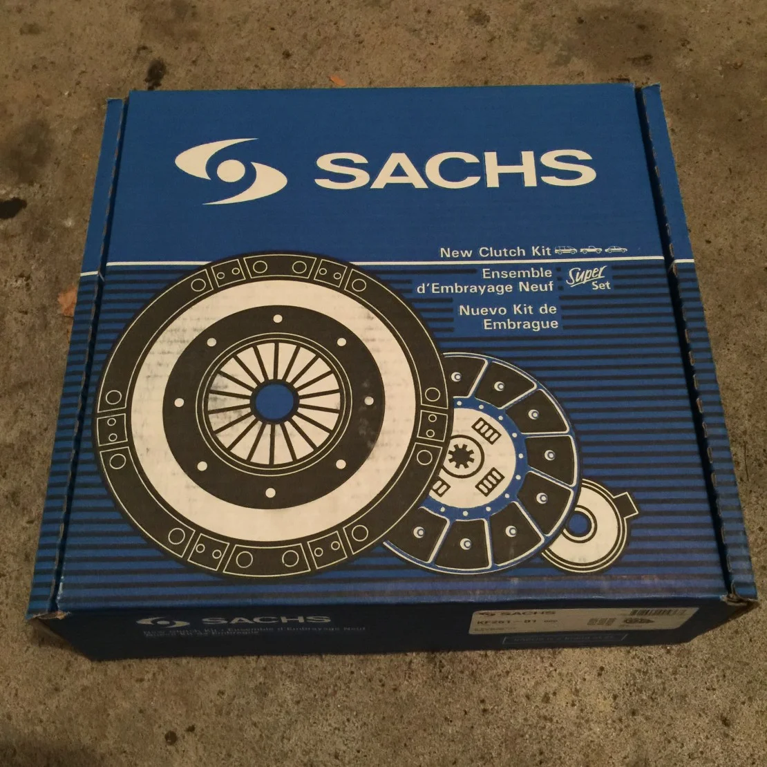
We opted for a new clutch as the age of the old one was unknown. This is super easy at this point. There's just a few bolts holding the clutch and flex plate on. Once removed they both will practically fall off. The throwout bearing is a little tricky to swap out, as the springs are a somewhat awkward to work with. Nothing too crazy though.


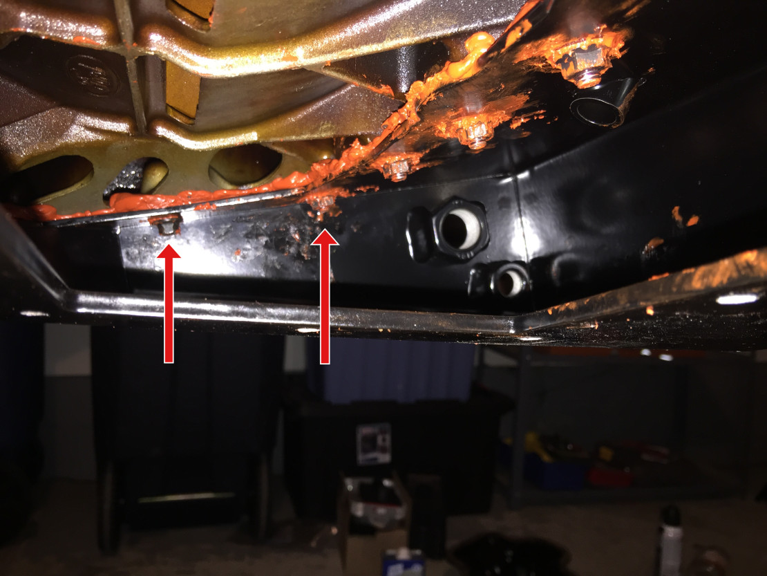
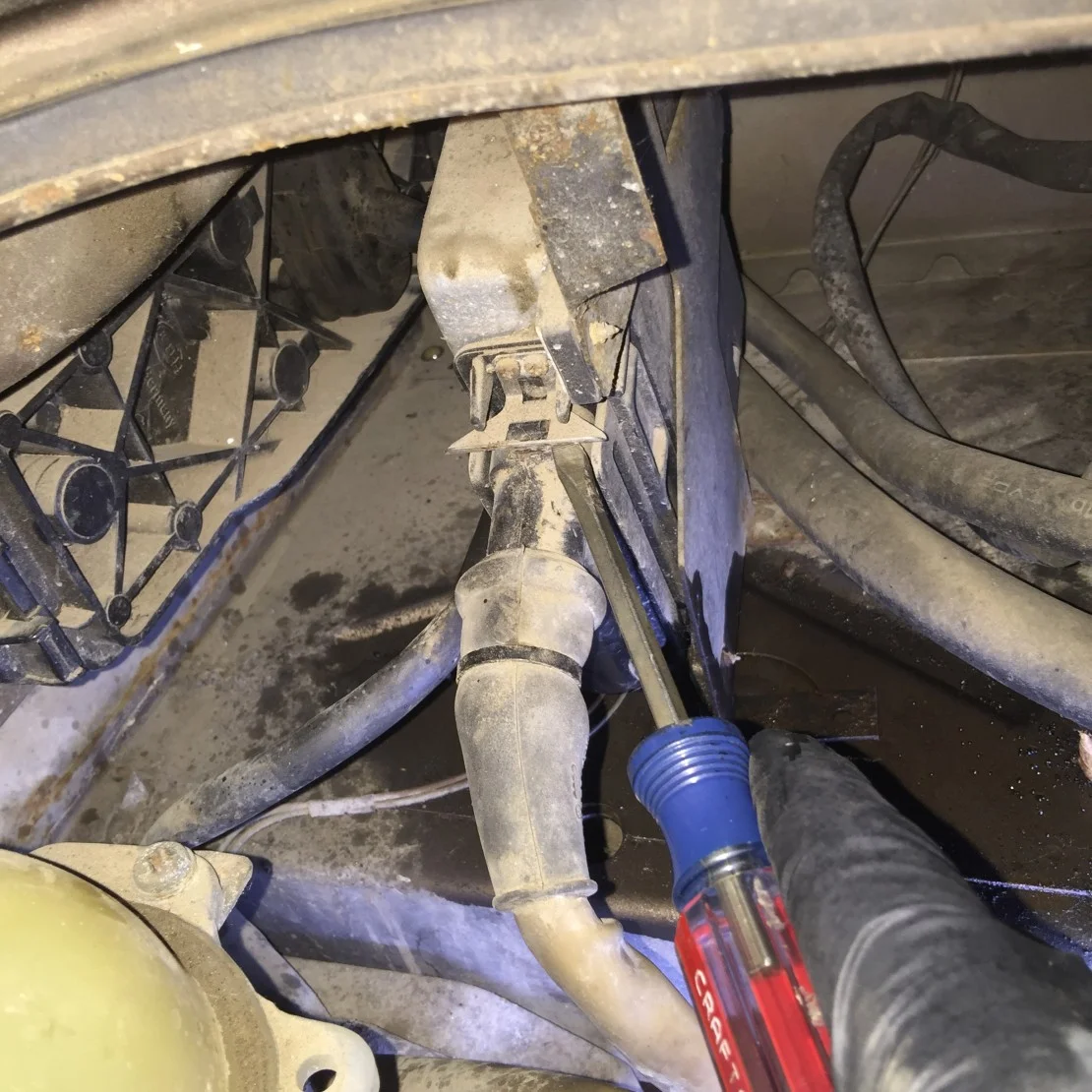
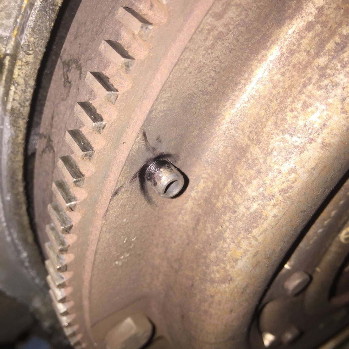
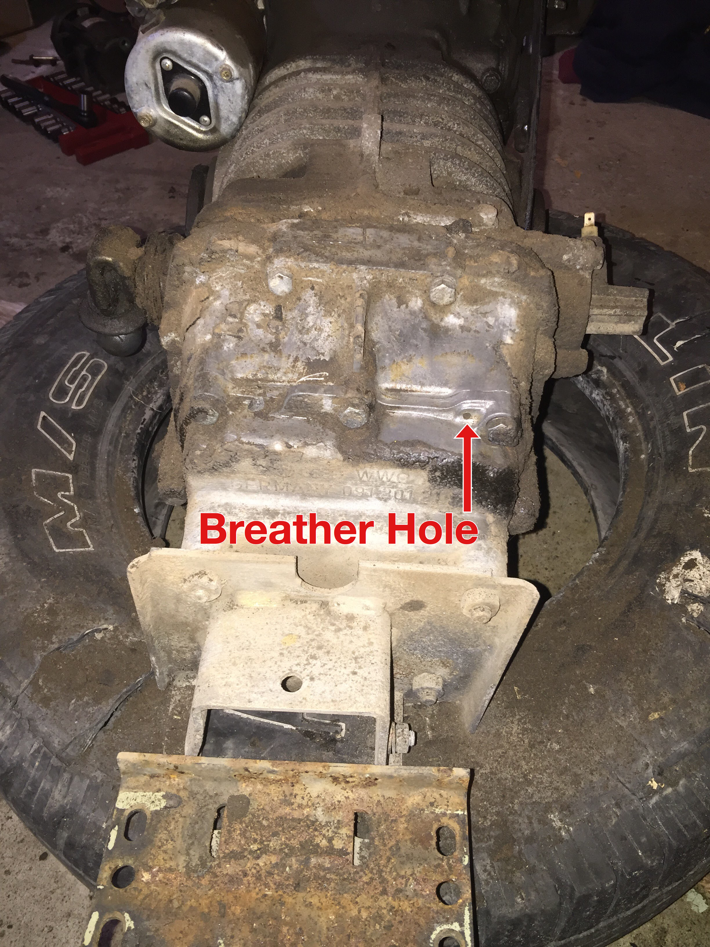
While you're in the area, make sure the breather hole on the front (as in front of vehicle, near the mounting plate, driver-side) of the transaxle is clear of debris. Ours was covered in about a ¼ inch of dirt. When I initially cleared the hole I could smell a wave of oil/gas fumes. That hole had probably been covered for years. The breather hole is meant to release excess pressure in the system, so definitely make sure it's clean. Try not to push the dirt and debris farther in; try and scrape / scoop it out. You'll need something with a pretty small tip.
Please note these pics were taken before I cleaned the hole out.

SK-C (Cooling), gaskets
Installed the two new gaskets and drilled the hole.


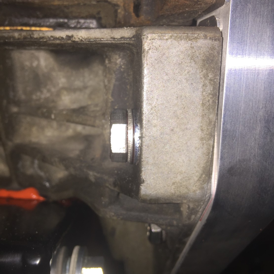
Exhaust bracket
I think the manual mentions something similar, but it's definitely nice to do this before you re-install the engine. Just gives you more space to work with.


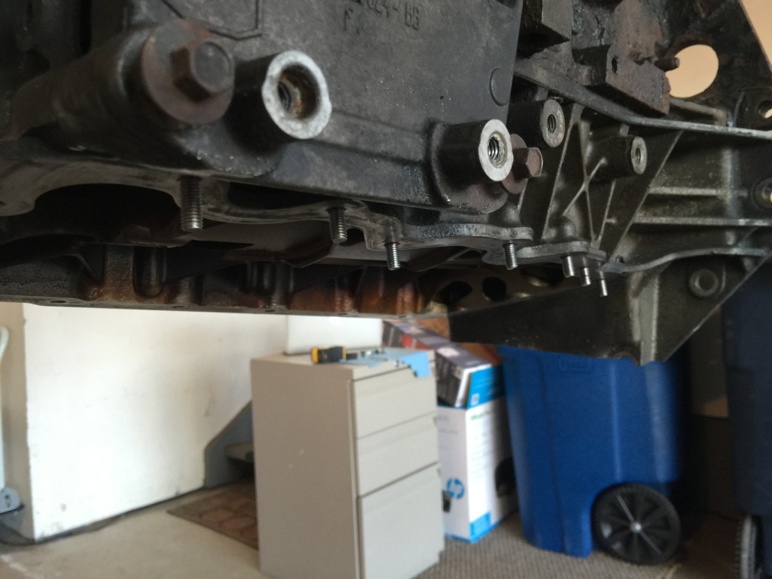
SK-M (Mounting), motor mounts and engine cradle
SK-M, prepping the motor mounts and engine cradle for install.


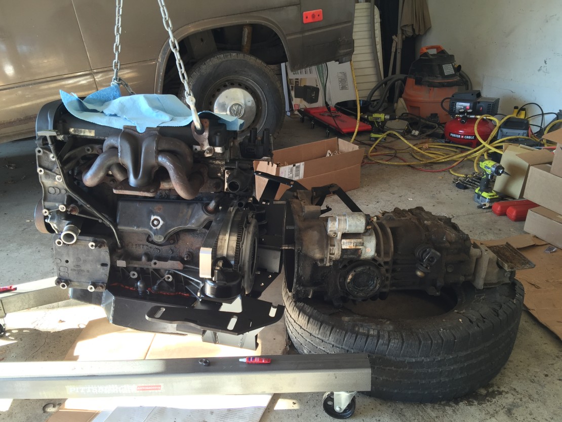
Zetec and transaxle mating
Another milestone! The Zetec and original Vanagon transaxle meet at last. The first picture shows you how NOT to do this. With both of them off of the floor it was very awkward with too many heavy, moving parts. Pics #2 and #3 shows you the right way. It seems rudimentary, but everything on the floor on top of some cardboard is the way to go. The transaxle lays slightly lower than the engine, so I simply added pieces of cardboard under the trans to slowly shim it up to the proper height. Everything was very stable this way.


That's it for Part 1, we're ready to start putting stuff back in the van! To see the completion of the conversion, be sure to check out Bostig Installation - Part 2!